DK Photonics offer optical passive component

About us

DK Photonics Technology Co., Limited is one of the leading companies in designing and manufacturing of high quality optical passive components mainly for telecommunication, fiber sensor and fiber laser applications. Headquartered and factory are located in Shenzhen of China. Cost effective, best quality and best service are always our goal.

DK Photonics produces a large array of fiber-optic components such as PLC Splitter, WDM, FWDM, CWDM, DWDM, OADM, Circulator, Isolator, PM Circulator, PM Isolator, Fused Coupler, Fused WDM, Collimator, Optical Switch and Polarization Maintaining Components, Pump Combiner, High power Components, Patch Cord and all kinds of connectors.High power components and polarization maintaining components are our major focuses. 

Optical Fiber In-line Polarizer & its Fine Features

The significance and value of Optical fibers don’t need any explanations or specifications in the world of electronics and technology. These devices are no doubt the tiny part but are equally important as well as requisite for the effective / efficient working of the machinery and electronic. When we talk about optical fiber In-line polarizer these are the cogs which can never be overlooked.

Optical Fiber In-line Polarizer

Low cost optical fiber In-line polarizer is the device to convert unpolarized light into linearly polarized light. It encompasses both, input as well as output as one input of single mode fiber and one output with polarization maintaining fiber. It can easily be connected conveniently into the optical systems through pigtailed input / output connectors.

Now let’s discuss the fine features of In-line Polarizer:

  • Low insertion loss: in telecommunications, the loss of signal power coming from the insertion of a device into the optical fiber is generally referred to as insertion cost. The insertion cost of the In-line polarization is stumpy and quite lesser than the other similar devices.
  • High extinction ratio: the polarizer especially, the In-line polarizer usually have the high extinction ratio i.e. the ratio of the two optical power levels of a digital signal produced by an ocular source.
  • High return loss: The optical fiber polarizer generates high return loss i.e. the loss of power in the signal reflected / returned by a discontinuity in a broadcast line or ocular fiber.
  • Compactness and light weight: Yet another beneficial feature of an In-line Polarizer is that it is quite compact as well as light weighted. This helps in the placement and execution of the appliance. Its light weight helps it work easily and effortlessly.
  • High stability and reliability: In-line polarizer is always recommended as it is quite stable as well as reliable. Unlike all other types of polarizers, the in-line polarizer has higher stability. This is the reason why companies and industries trust these.

Beyond all, the optical fiber In-line polarizer is available in market at low costs. There are several organizations which offer and sell the high quality optical fiber solutions at competitive prices and ensure you an effective as well as a durable working.

So, whenever you seek the high quality optical fiber In-line Polarizer, or decide to buy them, make sure you choose a copper-bottomed company to get the best products and high quality services as well as high class solutions at competitive prices!

DK Photonics – www.dkphotonics.com  Service to the factories, equipment manufacturers, operators and institutes who work for optical passive components, fiber communication, fiber sensing and high power laser applications, such as 1064nm High Power Isolator,1064nm High Power Circulator, Multimode Pump Combiner, Pump and Signal Combiner, Pump and PM Signal Combiner, Cladding Power Stripper, Polarization  Maintaining Optical Circulator, Polarization Maintaining Optical Isolator, Polarization Beam Combiner/Splitter, PM Filter WDM, Polarization Maintaining Filter Coupler, Polarization Maintaining Tap  Coupler, Polarization Maintaining Fused Coupler, Polarization Maintaining Fused WDM, In-line Polarizer.

10-Year Forecast – Fiber Optic Sensors

According to ElectroniCast, the combined use of Distributed and Point fiber optics sensors are forecast to reach $5.98 Billion in 2026…

 ElectroniCast Consultants, a leading market/technology forecast consultancy, today announced the release of their market forecast and analysis of the global consumption of Fiber Optic Sensors.

According to the study, the combined use of Distributed and Point (local) fiber optics sensors reached $3.38 Billion last year (2016), and the worldwide value is forecast to reach $5.98 Billion in 10-years (2026). Market forecast data in this study report refers to consumption (use) for a particular calendar year; therefore, this data is not cumulative data.

Both the American region and the EMEA region held similar market share in the overall (distributed- and point-types) fiber optic sensor value last year. The Europe, Middle East, Africa region (EMEA) held a very slight lead in relative market (value) share last year; however, the Asia Pacific region (APAC) is projected to take-over the leadership position during the forecast period.

The EMEA region is forecast to have a strong role in the use of distributed fiber optic systems, driven by the region’s use of systems in aviation, as well as in the

Petrochemical, Natural Resources, Energy/Utility application categories.

In terms of fiber optic point sensors, the American region is forecast to maintain the market share lead throughout the 1st-half of the forecast period (2016-2021), mostly led by the use of Fiber Optic Gyros (FOGs) in the Military/Aerospace application category. The consumption values are based on the end-user application and the end-user region.

FOGs held a 65 percent market share of the worldwide Point fiber optic sensor consumption value in 2016. “All regions, thanks mainly to increases in the use in aviation and military critical mission applications (Unmanned Aerial Vehicle/UAV and missile guidance, navigation, north finding/tracking, robotics, aviation and aeronautics and other) are forecast to show impressive increase consumption quantity (volumes) and values for the FOG systems,” said Stephen Montgomery, Director of the Fiber Optics Components group at ElectroniCast Consultants.

The market forecast of the Distributed Sensors is segmented by the following applications:

  • Manufacturing Process/Factory
  • Civil Engineering/Construction (buildings, bridges, tunnels, etc)
  • Military/Aerospace/Security
  • Petrochemical/Energy/Utilities/Natural Resources
  • Biomedical/Science

The Fiber Optic Point Sensor Forecast further segmented by the following sensing/measuring quantity (measurand) types:

  • Mechanical Strain
  • Temperature
  • Pressure
  • Chemical, Gas, Liquid
  • Vibration, Acoustic, Seismic
  • Displacement, Acceleration, Proximity
  • Electric, Current and Magnetic Field - Fiber Optic Sensors
  • Rotation (such as Fiber Optic Gyroscopes: FOGs)

“ElectroniCast counts each Point fiber optic sensor as one unit; however, the volume/quantity (number of units) of Distributed fiber optic sensors is based on a complete optical fiber line/link, which we classify as a system. Since a distributed optical fiber line (system) may have 100s of sensing elements in a continuous-line, it is important to note that we count all of those sensing elements in a distributed system as one (system) unit – only. Distributed fiber optic sensor systems involve the optic fiber with the sensors embedded with the fiber; also included is the optoelectronic transmitter/receiver, connectors, optical fiber, cable (fiber jacket) the sensor elements, and other related components,” Montgomery added.

According to ElectroniCast, the combined use of Distributed and Point fiber optics sensors reached $3.38 Billion in 2016…


Continuous Distributed and Point Fiber Optic Sensor

Global Consumption ($3.38 Billion in 2016)

Source: ElectroniCast Consultants


Tags: CWDM Multiplexer, DWDM Multiplexer,19" rack mount chassis CWDM, CWDM MUX/DEMUX Module, LGX CWDM Module,8CH CWDM Module, 16CH CWDM Module, 100GHz DWDM Mux/Demux, 200GHz DWDM Mux/Demux

DK Photonics – www.dkphotonics.com  specializes in designing and manufacturing of high quality optical passive components mainly for telecommunication, fiber sensor and fiber laser applications,such as 1064nm High Power Isolator,1064nm Components, PM Components, (2+1)x1 Pump Combiner,Pump Laser Protector,Mini-size CWDM,100GHz DWDM,Optical Circulator,PM Circulator,PM Isolator,Fused Coupler,Mini Size Fused WDM.

CWDM Mux & DeMux - Features and Applications

The CWDM are by and large in view of thin coat channel innovation which is the type of item fall under the WDM class. There arrived in a total scope of Class-8 CWDM Mux-Demux and also OADM that stands for Optical Add Drop Multiplexer units with a specific end goal to meet a wide range of necessities and system arrangements.

Likewise, it has across the board applications that require the Channel CWDM. Some of them include: Gigabit and 10G Ethernet, Fiber Channel, ATM, ESCON, in Metro total, SDH/SONET, and CATV and so forth. Presently, we should talk about the accompanying components and utilizations of Channel CWDM that settle on it an ideal decision for all. The CWDM Mux / Demux items give up to 16-channel or even 18-channel Multiplexing on a solitary fiber. Standard CWDM Mux/Demux bundle sort include: ABS box bundle, LGX pakcage and 19" 1U rackmount.

Highlights

  • The loss of insertion quality creates from the presentation of a gadget into the optical fiber is by and large lesser in CWDM than alternate gadgets; this produces short inclusion costs.
  • Channel-8 CWDM is dependably very steady and solid in the meantime. Not at all like every other sort of WDM class, the Channel CWDM has higher dependability.
  • The CWDM items are typically Epoxy free on optical way; this prompts better working and Epoxy free condition while the execution.
  • In CWDM, the channel segregation is very high. This expanded seclusion prompts better and successful outcomes.

Applications

WDM and Access Organize: As these channel sorts are the piece of WDM class, these have their best application in the WDM and also Access systems.

Line Observing: These items have their incredible use in line checking. This guarantees there is no crash on a similar line of some other range or frequency.

Cellular Application: The CWDM channel arrangements have their utilizations and applications additionally in the Cellular area, and advances as the unequaled panacea for some different parts and ventures.

Telecommunication: The broadcast communications devours Channel-8 CWDM at an incredible rate. It needs to utilize these items for the straightforward transmission of signs and utilization of the filaments for the same.

Aside from every one of the elements and applications, the capacity of CWDM is additionally to unravel the deficiency of fiber and straightforward transmission of exchange while lessening the charges of system building. This is the motivation behind why the Channel CWDM and LGX CWDM Mux and DeMux Module have a matter of extraordinary heights in the realm of fiber optics, flag transmission and multiplexing and so forth.

Understanding the Use of Optical Fused Coupler, MUX & DEMUX WDM

In today’s high tech world, there is a desperate need for bandwidth.  The development of WDM (wavelength division multiplexing) technology has greatly helped us to expand the network capacity over a single fiber. A fiber optic coupler is a device used in fiber optic systems with input fibers (single or more) and output fibers (single or more). It is different from WDM devices.

The main benefits of Optical fused couplers are as follows:-

  • Combining: This Fiber Optic Couplers combine two signals and yield single output.
  • Splitting: The Splitters supply two outputs by using the single optical signal.

On the other hand, WDM multiplexer and demultiplexer divide the different wavelength fiber light into different channels. WDM is further divided into CWDM (coarse wavelength division multiplexing) and DWDM (dense wavelength division multiplexing). Generally, the WDM systems operate on 9µm single-mode fiber optical cables although it is not necessary.

If we specifically talk about the CWDM method, CWDM multiplexes multiple optical carrier signals on a single optical fiber. It uses different wavelengths/colors of laser light combined in a MUX in order to carry different signals. Mux/DeMux is one of the most important components of CWDM systems.

The LGX CWDM Mux and DeMux module comes with a 8 Channel (dual fiber) with 1U 19 Rack Mount Box that utilizes thin film coating technology and proprietary design of non-flux metal bonding micro optics packaging. It has been designed to provide optical networking support over a grid of CWDM optical wavelengths in high-speed Fibre Channel and Ethernet communication for metropolitan area networks (MAN).

The optical component is easy to operate with a reliable low-maintenance design. The MUX is passive and it does not use power supplies or electronics. It is capable of multiplexing and demultiplexing ITU-T G.694.2 wavelengths up to 8 channels in increments of 20nm from 1270 nm to 1610 nm. “ITU” specifies the exact center of 8CH CWDM Mux and Demux dual fiber 1U 19 Rack Mount Box wavelength such as 1531nm, 1591nm, 1611nm, etc.

The 8 Channel CWDM Mux and Demux dual fiber 1U 19 Rack Mount Box are protocol and rate transparent. They allow different services up to 10Gbps transported across the same fiber link. It works seamlessly with transceivers to optimize the link length, signal integrity, and overall network cost. It can be incorporated into a single rack-mount solution for a better design, power, and space efficiency.

As per the working principle, MUX and DEMUX can be used in various fields, such as communication systems, computer memories, telephone networks, etc. It is a cost saving method of connecting a multiplexer and a demultiplexer together over a single channel.

How to get the Optical Fused Couplers, Mux and DeMux WDM?

There are several leading companies in market that are considered masters at the designing and manufacturing of optical passive components for fiber laser, fiber sensor, and fiber optic telecommunication applications. One can contact these companies to avail high quality opticalcouplers, Mux and DeMux at affordable rates.

Contact a supplier today and get them.

WDM And The Modules Based On It: The Need Of The Hour

In fiber-optic world of communication, wavelength-division multiplexing or WDM is an innovation which multiplexes various optical transporter signals onto a solitary optical fiber by utilizing distinctive wavelengths, that is the shades of the laser light. This system empowers bidirectional interchanges in more than one strand of fiber, and also increases the limits and domains of it. The term wavelength-division multiplexing is generally connected to an optical transporter, which is normally depicted by its wavelength, though recurrence division multiplexing is commonly applied to a radio bearer which is all the more of a frequently portrayer by recurrence. This is a simple convention since wavelength and recurrence convey a similar data.

How a WDM system works:

A WDM framework utilizes a multiplexer at the transmitter to combine the few signs and a demultiplexer at the collector to part them separated. Hence, WDM Mux and DeMux Modules are made to be used with the correct kind of fiber as it is conceivable to have a gadget that does both all the while, and can work as an optical add-drop multiplexer. The optical filtering gadgets utilized have ordinarily been etalons or to say, stable solid-state single-frequency Fabry–Pérot interferometers in the form of a thin-film-covered optical glass.

Need of WDM Multiplexing:

Since the physical fiber optic cabling is costly to actualize for every single company independently, its ability development by utilizing a Wave Division Multiplexing (WDM) is the need of the hour. WDM innovation was created to extend limits of single fiber systems can give. A WDM framework utilizes a Multiplexer at the transmitter to join a few wavelengths together; thus each one conveys diverse flag and signals via a demultiplexer at the recipient to make them separated. Both Mux and Demux are latent parts of the circuit, as their requirement of power is nil.

Types of WDM available:

These days there are a few sorts of institutionalized WDM in availibility:

  • General WDM, for example, 980/1550 WDM, 1310/1550 WDM.
  • CWDM incorporates CWDM mux/demux module and CWDM OADM module. The normal setup of CWDM mux/demux module is 2CH, 4CH, 8CH, 16CH, 18CH CWDM mux/demux module. Single fiber or double fiber association for CWDM Mux/demux are accessible.
  • DWDM incorporates 50GHz, 100GHz, 200GHz DWDM mux/demux module and DWDM OADM module. The normal arrangement is 2CH, 4CH, 8CH, 16 CH, 32CH, 40CH channels.
  • They are accessible as Plastic ABS module tape, 19'' rack mountable box or standard LGX box. What's more, regardless of what sort of connectors, as FC, ST, SC, LC and so on, all is available on DK Photonics, and they additionally can blend connector on one gadget. DK Photonics Technology Limited is one of the main organizations in outlining and assembling of fantastic optical inactive parts primarily for media transmission, fiber sensor and fiber laser applications. Headquarter and manufacturing plant is situated in Shenzhen of China. Savvy, best quality and best administration are forever their objective. So if you have any requirement regarding the WDM or any of the devises based on it, DK Photonics is the reliable and trusted brand!

Two Types Of Polarization Beam Combiners & Splitters

Polarizing Beam combiners / splitters are the devices used to combine two polarized light signals or split single non-polarized light into two polarized parts. These combiners and splitters are designed and developed to split light beams by deploying the polarization state and not by wavelength or intensity.

The polarizing beam splitters / combiners typically have 0° or 45° angle of incidence and a 90° division between the beams; this generally depends on the configuration. There are two types of Polarization beam combiners and splitters; these are described below:

  1. Incoherent Polarization Combining / Splitting

The Incoherent combining or splitting is the simpler variant and the basic technique. In this method, the resulted beams of two broad area laser diodes are sent onto a thin-film polarizer so as to reflect one of the beams while transmit the other; both of these beams then propagate in the same direction. As a result, one attains an unpolarized beam (with the combined optical power of the input beams) and the same beam quality. Consequently, the brightness gets nearly doubled.

This technique is often used for any-a-applications, for instance, end-pumping of a solid state laser with an increased power. However, the technique is not suitable for power scaling.

  1. Coherent Polarization Combining / Splitting

With coherent beam combining or splitting it is viable to attain a linear polarized state in the output, if two mutually coherent beams are combined. If two ports have the equal input powers, the output polarization would be typically rotated by 45° -depending on the polarization direction of any of the input beams.

Also, the coherent polarization combining can be repeated several times because of the linear output polarization. Thereby, this technique is suitable for power scaling.

A polarization beam combiner and splitter is often used in photonics instrumentation, optics and semiconductors to transmit p-polarized light while reflecting s-polarized light. These hold a world of worth when it comes to optics, telecommunication and fiber applications, and make the working effective as well as effortless.

Learning the Different Coating Stripping Methods

The cladding power stripper also referred to as the multimode optical power stripper is designed for amplifier applications and high power fiber laser. It is an ideal device  for ASE, residual pump power stripping, core modes that have escaped from double cladding fibers inner cladding while ensuring preservation of single power minimal degradation and beam quality (M2). Single power that is reflected into the inner cladding may also be stripped out too.  The handling capability of the stripping power goes to 800W or at times may be even higher

Stripping the Coating

The fibers that most reputable companies supply all come with a standard  acrylate single layer coating or, in some such as the high power products, a coating that is high temperature enduring. In comparison to dual layer coatings, the coatings that are single layer are more brittle and smooth. The coating can be removed readily using the conventional tools for fiber stripping such as the Fitel S-210 Clauss or CFS-1 for 125 μm cladding diameter fiber or for larger cladding diameters the Clauss No Nik stripper is used. For fibers whose outer diameter is non-standard, it is recommended that an adjustable stripper is used.  Thermal strippers such as those that are attached to the Schleuniger FiberStrip 7030 or the Vytran FFS-2000 can be used for all fiber in a safe way.

Alternatively, chemical stripping of fibers can be done using an appropriate solvent. For example, the coating can be exposed for one minute to sulfuric acid at 120°C sulfuric acid. Before the fiber is dipped into the liquid, the tip should be sealed with a drop of glue of 2 mm in diameter or through the end fiber hole collapsing using a fusion splicer.  It is worth noting that most glue types are dissolved in this acid, but epoxies that are two-component such as the Epotek ND353 tends to dissolve in a slower manner than the coating.

It is also possible to obtain chemical stripping through application on the fiber tip, of paint stripper. The paint stripper is usually in the form of a gel so as to reduce the occurrence of out-gassing and can be applied easily using a small brush. After a minute or so, the coating becomes soft and is removed easily using a lens tissue. It is worth noting that paint stripper typically contains dichloromethane (CH2Cl2) and as such there may be restrictions by local regulations to use it. For lower quality and faster stripping, another option would be to use a normal cigarette lighter to burn the coating off. However, the fiber may end up becoming brittle hence not the best choice for stripping.

Know the Difference between CWDM and DWDM

A WDM (Wavelength Division Multiplexing) is a system that uses a multiplexing (at the transmitter) and a demultiplexer (at the receiver) for the completion of the process and transmission of the signals.

The WDM is divided into three types (WDM, CWDM and DWDM) on the basis of wavelength difference among the three. The article discusses the main differences among CWDM and DWDM.


CWDM stands for Coarse Wavelength Division Multiplexing, and DWDM is the acronym for Dense Wavelength Division Multiplexing. Whether DWDM or CWDM, both are the types of WDM mechanism and have an array of differencess.

Let’s get acquainted with the chief difference between CWDM and DWDM:

  • The Coarse WDM has less than 8 active wavelengths per optical fiber whereas the DWDM has more than 8 active wavelengths per optical fiber.
  • The CWDM has lower capacity strength and hence is low in costs; conversely the DWDM possesses high capacity –this leads to an augmented price which is worth its qualities.
  • When it comes to the difference between the distance of the two, the CWDM has short range communication because the wavelength is not amplified, and DWDM has long range communication.
  • CWDM Mux and Demux systems are developed to be used in multiplexing multiple CWDM channels into one or two fibers.
  • Another major difference is that DWDM systems are made for longer haul transmittal, by keeping the wavelengths closely packed. Also, a DWDM device can transmit more data over long distances and to a significantly larger run of cable with lesser interference than a comparable CWDM system which has a shorter haul transmittal.
  • Furthermore, the Dense Wavelength Division Multiplying systems are capable to fit more than forty different data streams in the amount akin to that of fiber used for two data streams in a CWDM system.

Apart from all the difference there is one more and that is wavelength drift is possible in CWDM, but when it comes to the DWDM –precision lasers are needed to keep channels on the target.

Beyond being different from each other –these systems play different roles in the effective transfer of the signals, and thereby both are important enough.

Selection Guideline for Polarization Maintaining Optical Circulator

There are very many passive components involved in fiber optical networks and an optical circulator is among the top options. These components help in signal delivery without any failure thus remain to be very important. When used, the optical circulator will direct the signals between different ports but maintaining a single direction. There will be no chances of the signal going in a different direction that was not intended.

Two-way situations apply

However, that does not make it a one-direction device only. There are rare situations where you can have the circulator used in a two-way situation. When there is an optical signal sent by the circulator in two different directions, the fiber is usually one. You will have the circulator fixed on the two ends of the fiber and will function by adding a signal in one end while removing from the opposite end.

Whenever you are choosing a Polarization Maintaining Optical Circulator to use, there are very many things that must be put into serious consideration. That will be the benchmark on which your choices will be based upon. Features must be one of the things that you look out for in an ideal optical circulator. The good thing is that such a circulator comes loaded with more features to make your experience remarkable.

Consider different applications

The circulator comes with two main high-power options to choose from. You can go for either 1550nm or 1064nm depending on your needs. The other standout features for Polarization Maintaining Optical Circulator include epoxy-free optical path and compact inline package. There are additional features that as well make the circulator a unique choice compared to other alternatives available.

The other thing to look at includes applications which play a key role in the functioning of an optical circulator. Main applications that you should pay attention to are bidirectional pumping, fiber sensors, add-drop multiplexing, bidirectional signal transmission systems as well as coupling inline chromatic dispersion compensation devices.

With these applications, you are sure that your circulator will give out an optimal performance. You can have a Polarization Maintaining Optical Circulator used in multiple optical settings thus it will offer you limitless options. That is because they are unidirectional and non-reciprocating while their availability as three-port makes the circulator even more suitable. Do you know that it’s possible to use optical circulators in communication systems that are more advanced? Well, that is yet another of their biggest advantage over other types of circulators.

Get optimal performance

That is made possible by the fact that optical circulators come with a very small insertion loss while their isolation levels are very high. When used in advanced systems of communication, the circulators will come as any of the common applications. The result you get from using Polarization Maintaining Optical Circulator will depend largely on how you have chosen to use it.  If you make your decision well, the result will be good but if not then you will get a different result. It will all depend on your choices.

Pump and signal combiner for bi-directional pumping of all-fiber lasers and amplifiers(10)

7. Signal feedthrough of the fiber combiner

Besides the pump power handling and the pump coupling efficiency of a fiber combiner, it is important for fiber laser and amplifier applications to maintain the optical properties of the signal light propagating through the fiber combiner. In particular, during the fabrication of the fiber component, externally induced mechanical stress and perhaps a marginal fraction of thermal diffusion of the core dopants [19] can result in a high signal insertion loss in conjunction with a degradation of the signal beam quality. This behavior was expected for large mode area DC fibers with a very low core refractive index (NA ~0.06), and therefore possible beam quality degradations of the signal feedthrough light was investigated (in Section 7.1).

The uninterrupted signal core in the fiber combiner provides the possibility of passing a signal beam through the combiner in forward and backward direction. However, in the case of a backward propagating signal, the pump diodes need sufficient protection against the signal. Thus, in Section 7.2 we investigate the signal to pump isolation of a 4 + 1x1 fiber combiner in a fiber amplifier setup.

7.1 Signal insertion loss and beam quality

In order to determine possible beam quality degradation and a signal insertion loss caused by the signal feedthrough of the combiner, the setup depicted in Fig. 14

fiber combiner

Fig. 14 Setup for beam quality measurements, TF: target fiber, PBS: polarization beam splitter.was used. A signal at a wavelength of 1064 nm was launched into the core of a 2.75 m long Ytterbium-doped DC fiber (Nufern YDF-25/250), which is specified with a signal core diameter of 25 µm (NA 0.06) and a pump core diameter of 250 µm (NA 0.46). Thus, the parameters of the passive TF of the combiner were matched to the active fiber. The coiling diameter of the active fiber was 12 cm to maintain near diffraction limited beam quality [20]. The transmitted signal had a power of about 200 mW and was propagating in reverse direction through the fiber combiner. The beam quality measurements were carried out with a Fabry-Perot ring-cavity. With this cavity it was possible to determine the power fraction in higher-order transversal cavity modes with respect to the Gaussian TEM00 mode by scanning the length of the ring-cavity over a free spectral range (FSR). A detailed description of the measuring setup can be found in Ref [21]. Due to the use of a polarization sensitive beam quality measurement, a half- and a quarter-wave retardation plate in conjunction with a polarization beam splitter (PBS) were used. The determined polarization extinction ratio was better than 17 dB after the propagation of the signal through the active fiber and the fiber combiner.

Before the fusion splice between the active fiber and the 4 + 1x1 combiner, the power in higher-order modes of the active fiber was determined. This measurement served as a reference beam quality for the active fiber. The mode scan in Fig. 15(a)

fiber combiner 2

Fig. 15 Normalized transmitted intensity through a premode cleaner as a function of the ring-cavity length in units of a free spectral range for (a) the reference beam and (b) the signal feedthrough beam of a 4 + 1x1 fiber combiner.

shows the logarithmic normalized intensity over a free spectral range for the reference beam with a power in higher-order modes of 3.1%. This results in a fundamental fiber mode power of at least 96.9% for the reference beam. For the signal feedthrough of the fiber combiner, a power in higher-order modes of only 5.1% was found (Fig. 15(b)).

Consequently, the signal feedthrough fiber (0.7 m long TF) only led to an increase in power in higher-order transversal modes of maximal 2%. Furthermore, it must be considered that additional power transfer to higher-order transversal modes can also be caused by the fusion splice between the active DC fiber and the TF. Hence, good preservation of the signal beam quality, in conjunction with the low signal insertion loss of less than 3%, provides an excellent high power fiber component for monolithic fiber laser and amplifier systems.

Work Theory of the Laser Cutting Machine(2)

Cutting methods of laser cutting machine

Vaporization cutting

It means that vaporization is the main way to remove the processed material. In the process of vaporization cutting, workpiece surface is heated to vaporization temperature quickly by focused laser beams, forming High pressure steam and spraying outward at supersonic speeds. In the meantime, a hole is formed in the laser active area and laser beams reflex several times in the hole to increase the absorption of laser pump power combiner by material.

When high-pressure vapors spray outward, the melted materials are blown away in the kerf till the workpiece is finally cut. Vaporization cutting needs very high power density, which is eighth power of ten watt above per square centimeter. It is usually applied in low flash point materials and refractory materials.

Reaction Fusion Cutting

Reaction Fusion Cutting

When assistant airflow not only blows the melted materials from the kerf but also has thermal reaction with the workpiece, this is the so-called reaction fusion cutting. Gases that can have reaction with workpiece are oxygen or mixture gases containing oxygen. When the surface  temperature of workpiece reach to ignition temperature, strong combustion heat release occurs to improve the laser cutting ability.

Combustion heat release of low carbon steel and stainless steel is 60%. And it is about 90% for reactive metals like titanium.

Compared to vaporization cutting and general fusion cutting, reaction fusion cutting need less laser power density. However, reaction fusion cutting may effect the performance of worpiece since the combustion reaction can lead to chemical reaction on materials.

Fusion Cutting

When adding a assistant airflow system coaxial with laser to  blow the melted materials away from kerf, this kind of cutting is fusion cutting. In fusion fiber coupler cutting, workpiece needn't to be heated to vaporization temperature so the required laser power density is reduced greatly.

Laser Scribing

It is mainly used in semiconductor materials, in which laser of high power density make a shallow groove in the semiconductor materials of the workpiece and then makes it crack through mechanistic or vibratory methods. The quality is valued by the surface fragments and size of heat affect area.

Cold Chipping

It is a new processing method, which is put forward along with ultraviolet band superpower excimer laser appeared in recent years. The basic theory is that energy of ultraviolet photons is similar to binding energy of many organic materials; this high-energy photons are used to impact bond organic materials thus make it crack, achieving purpose of cutting. This new technology has promising application future, especially in electron industry.

Thermal Stress Cutting

Mechanism of thermal stress cutting is that laser beams heat an area of fragile material to produce evident temperature gradient. The high surface temperature makes expansion and inner lower temperature hinders expansion, forming pulling stress in the surface and radial crushing stress inside. When the two stresses exceed fracture limit strength of the workpiece, crackle appears. And then the workpiece is broken along the normal direction of the crack. It is suitable for glasses and ceramics.

Conclusion: laser cutting machine is a cutting technology of melting and gasifying surface material through focused energy generated by the use of laser specialties and focused lens. It features good cutting quality, high speed, various cutting material and high efficiency.

About DK Photonics

DK Photonics – www.dkphotonics.com  specializes in designing and manufacturing of high quality optical passive components mainly for fiber laser applications such as 1064nm high power isolator, Cladding Power Stripper, Multimode High Power Isolator, pump combiner,1064nm Band-pass Filter,(6+1)X1 Pump and Signal Combiner, PM Circulator, PM Isolator, optical Coupler. More information, please contact us.


Work Theory of the Laser Cutting Machine(1)

Laser has been applied in teaching, military as well as industrial production. Laser cutting machine is one of the applications. It can be used in both metal and non-metal cutting, Melting surface material by laser beam. This article will discuss the work theory of laser cutting machine.

Introduction on the work theory of laser cutting machine

Introduction on the work theory of laser cutting machine.

Laser cutting machine adopts the energy released on the time when laser beam irradiate metal surface. The metal is melt by laser and sinter is blow away by gas. Because laser power is highly focused, only a very little heat effects the other part of metal plate and causes a little or no deformation. Laser can cut any complex shape precisely, which needs no further processing.

Laser source is generally CO2 laser beam high power isolator with operating power of 500~5000W. The power is even lower than that of many household electric heater, and because of lenses and reflectors, laser beams are focused in a very small bit of area. Highly focused energy heat the area quickly and makes the metal plate melted.

Laser cutting machine can cut stainless steal of thickness less than 16mm; when adding oxygen in laser beam, the cutting thickness is 8~10mm but it will generate a thin oxidation film in the cut surface. The maximum thickness is 16mm which leads to larger cutting deviation on the size of components.

Since the advent of laser, numerous laser products have been developed, such as laser printer, laser cosmetic instrument, laser marker, laser cutting machine etc. Due to its late start in China, the laser technology in China is greatly behind the developed countries. Although Chinese manufacturers can produce plenty of laser products, some key parts such as laser tube, driving motor, galvanometer and focus lens are imported products. This leads to an increase on cost thus an increase on consumer's payment.

In recent years, domestic research and production of  laser products become closer to advanced overseas products with the progress of laser technology in China. Some aspects are even superior to products abroad, which has a leading role in market because of the  advantages of price. Overseas products have absolute predominance in precision machining for its quality on stability and endurance.

Work theory of laser cutting machine

Work theory of laser cutting machine

Laser tube is the core part of laser cutting machine. So, below is an introduction of the most popular laser tube. CO2 laser tube.

Laser tube is composed of hard glasses, so it is fragile. It adopts layer of sleeve construction with discharge tube in the most inside layer. However, the diameter of discharge tube is thicker than laser tube, diffraction between the thickness of discharge tube and the size of flare is in direct ratio; the length of tube is in proportion to output power of discharge tube.  Laser tube generates a large quantity of heat in the operation of laser cutting machine, which influences the normal work. So cold water machine is needed to cool laser tube, ensuring constant temperature for successful running.

Cutting features of laser cutting machine

Advantages of laser cutting:

One — high efficiency

Laser cutting machine is always connected to several numerically-controlled rotary tables to achieve numerical controlled cutting. It only needs to change the NC program to adjust to components of different shapes, which can make 2D cutting as well as 3D cutting.

Two — high speed

When cutting low carbon steel sheets of 2mm thickness, the speed of 1200W laser cutting is 600cmmin; when it is 5mm thick polypropylene resin plate, the cutting speed is 1200cmmin. The material needs no clamping fix in laser cutting process.

Three — high quality cutting

Laser cutting features thin kerf. The two sides of kerf are parallel and the kerf is vertical to the surface. The cutting precision can reach to ±0.05mm. The cutting surface is clean and nice, with roughness of tens of microns. The cut components can even come into use directly without further machining. After laser cutting, the heat effected area is very small and material near to kerf has not been affected, making little deformation, high cutting precicion and perfect geometrical shape

Four — non-contact cutting

Laser cutting is non-contact cutting, which means no tool wear problem. When processing different shapes, there is no need to change tools, the only way is to alter the output parameter of laser. The whole laser cutting process features low noise, little vibration and little pollution.

Five — various cutting material

Compared to oxyacetylene cutting and plasma cutting, laser cutting can be applied on more materials, including metal and non-metal, metal matrix and non-metallic matrix composite, leather, wood as well as fibers.

About DK Photonics

DK Photonics – www.dkphotonics.com  specializes in designing and manufacturing of high quality optical passive components mainly for fiber laser applications such as 1064nm high power isolator, Cladding Power Stripper, Multimode High Power Isolator, pump signal combiner,1064nm Band-pass Filter,(6+1)X1 Pump and Signal Combiner, PM Circulator, PM Isolator, optical Coupler. More information, please contact us.

Pump and signal combiner for bi-directional pumping of all-fiber lasers and amplifiers(9)

6. Demonstration of 440 W pump power handling

After detailed theoretical and experimental characterization of fiber pump combiners with multiple pump ports, a pump power handling performance test was conducted. For these investigations each pump port of a 4 + 1x1 combiner was connected to a fiber coupled pump diode (nLight Pearl) with an output power of ~110 W at a wavelength of 976 nm. The PFF and the delivery fiber of the pump diode had a core diameter of 105 µm with a NA of 0.22. At each fiber output end of the IF, a pump light stripper was applied to avoid the Fresnel reflection of the TP, and therefore the TP was not measured. Up to the maximum total pump diode power of 440 W, a coupling efficiency of 90.2% was experimentally determined (Fig. 13

fiber pump combiners

Fig. 13 Combined pump power for a 4+1x1 high power fiber combiner, * ratio of coupled power to total diode power in percent.

). In the simulations a slightly higher coupling efficiency of 92.8% was obtained. The difference of 2.6% in simulated and measured pump light coupling must be distributed among TP, PAA and PCT, with simulated values of 3.0, 1.4 and 1.7%, respectively. It can be assumed that the PAA-fraction is higher than 1.4%, since the fibers of the combiner are contaminated with dust particles in spite of intensive cleaning. If we assume for each individual loss mechanism an error of 1% related to the total diode power then PCT was 7.5 W ± 4.4 W, i.e. the coating of the TF and the pump power stripper had to handle this fraction of power.

About DK Photonics

DK Photonics – www.dkphotonics.com  specializes in designing and manufacturing of high qualityoptical passive components mainly for fiber laser applications such as 1064nm high power isolator,Cladding Power Stripper, High Power Isolator,pump combiner,1064nm Band-pass Filter,(6+1)X1 Pump and Signal Combiner,PM Circulator,PM Isolator,optical Coupler.More information,please contact us.


Fiber Laser Welding: Some Traits and Applications(2)

Technological parameter of laser welding:

(1) Power density

Power density is one of the key parameters in laser processing. When the power density is relatively high, the surface would be heated to boiling point in microseconds, thus generate mass vaporization. As a result, high power density is good for material removal processing such as punching, cutting and carving. When the power density is relatively low, it would take some microseconds to meet the boiling point, the bottom can reach the melting point before vaporization occurs, thus a good melt welding is successfully formed. So the power density ranges from 104~106W/cm2 in conductive laser welding.

(2) Laser pulse shape

Laser pulse shape is an important question in laser welding, especially for foil welding. When high strength laser beam reaches the material surface, 60~98% of the laser energy will be lost by reflection and the reflectivity is changeable by the temperature of the material surface. The reflectivity of metal can vary greatly in a laser pulse period.

(3) Laser pulse width

Laser pulse width is an important parameter to distinguish material removal and material melting; it is also a key parameter to decide the cost and volume of processing equipment.

(4) Influence of defocusing amount on weld quality

There are two ways of defocus: positive defocus and negative defocus. It is positive defocus when focal plane is above the workpieces, vise versa. According to geometry optical theory, when positive and negative defocusing plane equals to welding plane, the power densities are almost the same in the corresponding panels, but the actual laser pools have different forms. It can achieve larger depth of fusion when it is negative defocus.

Application field of laser welding

Laser welding machine has wide application in manufacturing industry, powder metallurgy field, automobile industry, electronics and some other fields.

fiber laser 3

Source : demarlaser

Application of laser welding in automobile industry

Volkswagen AG has adopted laser welding in car roof of brands like AudiA6, GolfA4 and Passat. BMW and GM have used laser welding in top of the car frame while Mercedes-Benz has applied laser welding in drive disk assembly. Except for laser welding, other laser technologies have be applied as well. Companies like Volkswagen GM, Benz and Nissan have used laser to cut covering parts while FIAT and Toyota have adopted laser for coating engine exhaust valve; Volkswagen has used laser for surface hardening on engine camshaft. Domestic vehicle models like Passat, Polo, Touran, Audi, Dongfeng Peugeot and Focus have adopted laser welding technology.

Independent automobile brands like Brilliance, Chery and Geely have adopted laser welding as well.

Improvement and development of new laser welding technology

Laser welding technology is continuously developing along with the progress of the time. The following three technologies can help expanding laser's application scop and enhancing the automatic control level of laser welding.

  1. filler wire laser welding

Laser welding generally doesn't fill wires but has high requirement on assembling clearance, which is hard to be guaranteed thus limits the application scope. Filler wire laser welding method has lower requirement on assembling clearance. For example, if the aluminum alloy plate is of 2 mm's thickness, the clearance must be zero for a good shaping. When adopting φ1.6mm welding wire as filler metal, it can form good shape even the clearance is 1.0 mm. Besides, filler wire can be used for adjusting chemical components and multi-layer welding on thick board.

  1. Beam rotation laser welding

By the adoption of laser beam rotation laser welding methods, demands on welding assembly and beam centering are reduced greatly.

  1. On-line detection and control of laser welding quality

It is becoming a hot researching topic on detecting laser welding process by using plasma such as light, sound and electric charge; some researches have achieved closed-loop control.

DK Photonics – www.dkphotonics.com  specializes in designing and manufacturing of high quality optical passive components mainly for fiber laser applications such as 1064nm high power isolator, Cladding Power Stripper, Multimode High Power Isolator, pump combiner,1064nm Band-pass Filter,(6+1)X1 Pump and Signal Combiner, PM Circulator, PM Isolator, optical Coupler. More information, please contact us.

Fiber Laser Welding: Some Traits and Applications(1)

What is fiber laser? The world's first laser beam is produced in 1960 by the use of flashbulb stimulating ruby crystalline grain. Limited by the thermal capacity of the grain, the pulsed beams is short and the frequency is very low. Although the instantaneous pulse peak can reach up to 106W, it still belongs to low energy output.

fiber laser 1

Source:tamu.edu

Laser technology adopts the beams of light generated by the reflection of laser from polariscope and congregates the beams in focusing device to generate beams with enormous energy. Once the focus is approaching, the workpieces will be melt or vapored in some milliseconds. This opens up a new welding application domain for high power CO2 and high power YAG laser. The key of laser welding equipment is high power laser, including solid laser and gas laser. Solid laser is the so called Nd:YAG laser. Nd is a rare earth elements and YAG represents Yttrium Aluminum Garnet, with similar crystal structure as ruby. The wavelength of Nd:YAG laser is 1.06μm. It can produce beam transmitted by fiber, so it can simplify beam delivery system, which is suitable in flexible manufacturing systems and remote working as well as high welding precision workpieces. Nd:YAG laser of 3-4 KW output is commonly used in automobile industry. Gas laser is the so-called CO2 laser. Its working medium is molecule gases which can generate iraser of 10.6μm in average. It can work continuously and output very high power; the standard laser power is between 2-5 KW.

The major traits of laser welding are as following:

  1. The welding is fast and deep with little deformation.
  2. It can work in room temperature and disparity conditions with simple equipment and device. For example, the laser beam will not offset; laser welding can be really carried out in vacuum, air or any gas environment, or even through glass or any transparent material.
  3. It can weld refractory materials as titanium and quartz and anisotropic materials with good effects.
  4. When welding, depth-to-width ratio can reach to 5:1 and the highest can reach up to 10:1.
  5. It can applied in microwelding. Slight flare can be generated by focused laser beams which can positioning precisely and be applied in mass automatic production of micro and small workpieces' installation and welding.
  6. It is flexible in welding areas that is difficult to access. Especially in recent years, the adoption of optical fiber transmission in YAG laser processing technology has greatly promoted the popularization and application of laser welding technology.
  7. Beam split is easy to be realized by time and space and multiple beam can be processed all at once, providing conditions for more precise welding.

However, there are some limits of laser welding:

  1. It requires high assembly accuracy for weld and it should has no obvious deviation of beam on workpieces. It is because that the flare is too small and the welding line is too narrow. If the assembly accuracy and beam position cannot meet the requirements, it is easy to make weld defect.
  2. The cost and initial investment on laser and the relevant systems are high.

fiber laser 2

Resource : avio

DK Photonics – www.dkphotonics.com  specializes in designing and manufacturing of high quality optical passive components mainly for fiber laser applications such as 1064nm high power isolator, Cladding Power Stripper, Multimode High Power Isolator, pump combiner,1064nm Band-pass Filter,(6+1)X1 Pump and Signal Combiner, PM Circulator, PM Isolator, optical Coupler. More information, please contact us.


The Comparative Between Fiber Laser Cutting Machine and CO2 Cutting Machine

Cutting is one of the most widely applied laser processing techniques. Fiber laser and CO2 laser are the most commonly used laser cutting equipment. It is necessary for users to have a knowledge of the advantages and disadvantages of both the two ways of cutting.

CO2 laser

Source : fe.infn

Wavelength of fiber laser is 1.06μm and Wavelength of CO2 laser is 10.6μm. Both are infrared light and can be absorbed by material so that they can be applied in Industrial material processing. Fiber laser is unable to be applied in non-metal cutting, such as wood, plastic, leather and ramie cotton fabric. In case of non-metal cutting, CO2 laser is the only choice. But CO2 laser cannot cut copper products, including brass and red copper. Because copper is highly reflective material for CO2 laser, laser will be reflected instead of absorbed by copper, which can cause harm.

Laser is evaluated by integrated index as cutting speed, drilling efficiency and section quality.

Fiber laser has an advantage in cutting thin plate, especially for thickness under 3mm. Its maximum cutting speed ratio can reach to 4:1 and 6mm is critical thickness for the two kinds of lasers. When it is thicker than 6mm, fiber laser shows no preferential; as the thickness increases, CO2 laser shows preferential gradually but not outstandingly. Generally speaking, fiber laser has an advantage in cutting speed.

Drilling efficiency:

Before cutting, laser beam should penetrate workpiece. Fiber laser needs more time in drilling than CO2 laser. Take 3KW optical fiber laser and CO2 laser as an example, The latter saves 1 second in drilling 8mm carbon steel; and 2 seconds in 10mm drilling. As thickness grows, CO2 laser will save more time.

Fiber laser

Source : nufern

Section quality:

Section quality usually means the roughness (surface perfection) and perpendicularity.

When cutting steel plate under 3mm, section quality of fiber laser is worse then CO2. As thickness grows, the difference becomes more obvious.

In addition, carbon steel plate has high absorptivity on fiber laser energy, so it has shortcoming in cutting holes (aperture < panel thickness).

The above comparison will help users make a reasonable choice. The cutting speed of the two lasers is equally matched. Fiber laser is inferior to Co2 laser in section quality and drilling efficiency. There is no quick answer to which is better. They both have advantages and disadvantages in specific application demands.

By the way, laser cutting precision has nothing to do with the adoption of lasers. It is determined by machine positioning precision, resetting precision and consistency of kerf width. Fiber laser has narrower kerf than CO2. Kerf width doesn't affect precision of the parts either, since it can be offset by cutting gap compensation.

DK Photonics – www.dkphotonics.com  specializes in designing and manufacturing of high quality optical passive components mainly for fiber laser applications such as 1064nm high power isolator, Cladding Power Stripper, Multimode High Power Isolator, pump combiner,1064nm Band-pass Filter,(6+1)X1 Pump and Signal Combiner, PM Circulator, PM Isolator, optical Coupler. More information, please contact us.

Field-Terminated Fusion Splice-On Connector-North American Market Forecast

According to ElectroniCast, the quantity of field-terminated fiber optic splice-on connectors in North America will increase at an explosive annual rate of 41.9% …

ElectroniCast Consultants, a leading market research & technology forecast consultancy addressing the fiber optics communications industry, today announced the release of a new market forecast of the consumption of field terminated fiber optic fusion splice-on connectors in North America.

Fusion_Splice_on_Connector

Field terminated fiber optic fusion Splice OConnectors (SOC) are installed for rapid repairs or for limited space situations where pre-terminated fiber cabling may be difficult, such as when the cable assembly needs to pass through small openings such as conduit.  The splice-on connectors are an option when the precise length of the optical fiber link is not pre-determined and a field-installed termination solution is required, such as in Fiber to the Home (FTTH) and other communication applications.

Last year, 306-thousand field-terminated fiber optic fusion splice-on connectors were installed in non-OEM applications in North America.  The number of connectors is forecast to increase at an explosive rate of 41.9% per year, reaching 2.49 million units in 2020.  Market forecast data in this study report refers to consumption (use) for a particular calendar year; therefore, this data is not cumulative data.

The Telecommunications application category is forecast to maintain the leadership in relative market share through the year 2018, until the Premises Networks application category is set to capture the lead.  Telecommunication use is forecast for 35.5% annual growth in quantity (2014-2020), mainly driven by access optical fiber deployment.  The Cable TV application is also driven by the use of connectors for FTTH (Home) and FTTB (Building/MDUs – Multiple Dwelling Units).

The market forecast segments the connectors by single-mode and multimode optical fiber, as well as into the following types: MPO, LC, FC, ST, SC, and other.  The use of single mode fiber optic field-terminated fusion splice-on connectors in North America is forecast to increase from 173.8-thousand units in 2014 to 1.49 million in 2020.  Multimode fiber is best suited for use in short lengths, such as those used in datacom and specialty networks and in 2020, multimode connectors are expected to reach 1-million units.

“In 2014 in North America, 4.3-thousand new fusion splicers were brought into Premises Datacom, and the use of field terminated fusion splice on connectors is a major market driver for the use of fiber optic fusion splicers used in premises network applications, the data center (DC) and longer link length datacom cable installations,” said Stephen Montgomery, Director of the ElectroniCast market study.

“The SOCs are emerging as a viable alternative to pre-terminated fiber optic cables (pigtail and cable assemblies/ patch cords).  Also, based on primary research interviews with network planners and installers, we are finding that field terminated fusion splice-on connectors are rapidly being accepted as a go-to solution.  With SOCs, communication network technicians can install reliable cable links with exact lengths, eliminating cable shortness or excess slack that is typically a result with the pre-terminated cable solution,” Montgomery added.

Tags: CWDM Multiplexer, DWDM Multiplexer,19" rack mount chassis CWDM, ABS plastic box, CWDM MUX/DEMUX Module,  LGX CWDM Module,8CH CWDM Module, 16CH CWDM Module

The Modern Data Center – Modular Data Center

The modern data center is a complex place. The proliferation of mobile devices, like tablets and smartphones, place an ever-increasing pressure on the IT departments and data centers. End-user and customers’ expectation levels have never been higher and the demand for data shows no sign of slowing down. Data center managers must manage all of these elements while also remaining efficient and keeping costs under control. So where does the data center go from here?Modular Data Center

One thing I have noticed in the evolution of the modern data center is that the facilities are gaining importance; improving energy efficiency and IT management have come to the forefront. Maximizing the organization’s resources is vital, and that means delivering more to facilities and equipment without expending more on staffing. IDC forecasts that during the next two years, 25 percent of all large and mid-sized businesses will address the power and cooling facility mismatches in their data centers with new IT systems and put a 75 percent cap on data center space used. So there again is the crucial challenge of doing more and innovating while keeping budgets and spend under control.

Another key part of the next generation data center mix is automation. Today’s data center manager is engaged in sourcing the right automation tools that will help them manage energy consumption and add new technology without disrupting normal operations. These are a few of the key challenges in the modern data center—so data center managers and IT departments must find ways to address them.

Where does the Data Center Go Next?

At the heart of data center evolution is the information technology sector’s rapid rate of change. Many new products and services must be implemented with much less time to value, and data centers need to be agile enough to assess and accommodate them all. If you examine enterprise data centers, then you might observe the ways that cloud computing and hyperscale innovations are displacing traditional enterprise systems, with new paradigms pioneered by innovators like Amazon and Google. With new options being developed, enterprises now have to chart strategies for cloud computing, including public, private or hybrid cloud. Gauging where the technology will go next is difficult to tell. Will the traditional vendors, such as Cisco and EMC, prevail or will new paradigms from Nutanix or Simplivity disrupt and displace these traditional data center dominators?

The race is on to manage the rapid rate of change while also staying agile, meeting end-user expectations and managing costs. For example, data center managers must handle the level of capacity their data center requires while ensuring they don’t overspend on unused capacity. This is where the focus on data center design comes into play.

Taking the Data Center Forward

These specific needs and challenges that the modern data center faces require working with the right tools and solutions. Modular, purpose-built data center infrastructure allows organizations to develop data center services based on need—when capacity rises and where capacity is needed. For example, we’ve observed in Singapore that most data centers operate slightly above 2.1 Power Usage Effectiveness (PUE). This means that companies spend more on cooling their data center rather than on operating and powering the IT equipment. It is a simple challenge—drive efficiency without impacting operations. You want to drive PUE down to approximately 1.06, regardless of where you need to operate, and reap huge energy savings while better serving customers. If done right, there is a positive environmental impact.

Changing the paradigm of the traditional data center enables organizations to reap these rewards. Assessing and establishing business objectives that reflect what is possible, rather than what always has been or what is easier and more comfortable, has led to innovative services and new business models that reset the competitive standards for everyone. Better PUE is a mandatory step in this process. The PUE journey continues as evidenced by Amazon, which had recently taken to harnessing wind to power its data centers. Modular data centers will play a major part in this PUE journey, thanks to more efficient use of energy and greater flexible support for resiliency and compute density.

How much do you know about CWDM Multiplexer and DWDM Multiplexer

CWDM multiplexer and DWDM multiplexer are two main products of WDM multiplexer. The full name of WDM, CWDM and DWDM are wavelength division multiplexing, coarse wavelength division multiplexing and dense wavelength multiplexing respectively. How much do you know about them? If you have no idea, the following introduction will help you a lot.

In the very first place, let's get to know what the WDM is. Based on a single fiber optic transmission, many optical signals that are loaded with information and have different wavelengths can be synthesized into one single beam by WDM multiplexer. Then, a special communication technology will be adopted to separate those optical signals at the receiving terminal. On the basis of WDM technique, the CWDM device and DWDM device are two popular products in the current market.

CWDM device

When it comes to the CWDM multiplexer, first of all, it provides service for metropolitan area network access layer, whose working principle is in line with WDM multiplexer. However, it simplifies the structure largely. For example, the filter film layer number of CWDM is just 50, while the WDM is as many as 200 layers. That is to say, the rate of finished products has been improved and the cost has been reduced largely. Besides low cost, the CWDM device is also advantageous in small volume, small power consumption, convenient maintenance and large transmission capacity. The laser device in the system doesn't need semiconductor refrigerator and temperature controller, which can lessen the power consumption obviously. However, the CWDM also has shortcomings. For instance, developing and simplifying the optical transceiver module and optical component is urgent to be solved.

DWDM device

As to the DWDM multiplexer, comparatively speaking, it makes the best use of fiber-optical bandwidth and enhances the message capacity of cellular system, which is well-known for simple dilatation and stable performance. Integrated system and open system are two dominant application systems of DWDM multiplexer, which are based on different wavelength conversion technologies. No matter which system is adopted, the free-running 1510nm wavelength will be chosen to carry OSC or optical supervisory channel so as to transmit information. Such an OSC is a comparatively independent subsystem, which offers maintenance and management information.

The last question is what advantages WDM technique has when compared with traditional transmission methods. Generally speaking, it includes such aspects as making best use of low-loss wave band, transmitting several optical signals in one optical fiber, good flexibility, low investment cost, excellent system reliability and fast and convenient recovery.


Tags: CWDM Multiplexer, DWDM Multiplexer,19" rack mount chassis CWDM, ABS plastic box, CWDM MUX/DEMUX Module,  LGX CWDM Module,8CH CWDM Module, 16CH CWDM Module

Do you know these about CWDM Multiplexer and DWDM Multiplexer?

Do you know these about CWDM Multiplexer and DWDM Multiplexer?

Wavelength division multiplexing (WDM) is a technology or technique modulating numerous data streams, i.e. optical carrier signals of varying wavelengths (colors) of laser light, onto a single optical fiber. The goal of WDM is to have a signal not to interfere with each other. It is usually used to make data transmission more efficiently. It has also been proven more cost effective in many applications, such as WDM network applications, broadband network application and fiber to the home (FTTH) applications and so on. According to channel spacing between neighbored wavelengths, there are two main types of WDM, including Coarse WDM (CWDM) and Dense WDM (DWDM). Though both of them belong to WDM technology, they are quite different. Then, what are the differences between them? This paper will give you the answer.

Definition of CWDM

CWDM is a method of combining multiple signals on laser beams at various wavelengths for transmission along fiber optic cables, such that the number of channels is fewer than in DWDM but more than in standard WDM. “Course” means the channel spacing is 20nm with a working channel passband of +/-6.5nm from the wavelengths center. From 1270nm to 1610nm, there are 18 individual wavelengths separated by 20nm spacing.

Definition of DWDM

DWDM is a technology that puts data from different sources together on an optical fiber, with each signal carried at the same time on its own separate light wavelength. “Dense” refers to the very narrow channel spacing measured in Gigahertz (GHz) as opposed to nanometer (nm). DWDM typically uses channel spacing of 100GHz with a working channel passband of +/-12.5GHz from the wavelengths center. It uses 200GHz spacing essentially skipping every other channel in the DWDM grid. And it has also gone one step further using an Optical Interleaver to get down to 50GHz spacing doubling the channels’ capacity from 100GHz spacing.

CWDM vs DWDM

According to the content above, you will find some small differences between them. 16CH CWDM Module is defined by wavelengths and has wide range channel spacing. DWDM is defined by frequencies and has narrow channel spacing. What’s more, what other differences do they have?

Capacity of Data

In fiber optic network system, DWDM system could fit more than 40 different data streams in the same amount of fiber used for two data streams in a CWDM system. In some cases, CWDM system can perform many of the same tasks compared to DWDM. Despite the lower transmission of data through a CWDM system, these are still viable options for fiber optic data transmission.

Cost of Cable

CWDM system carries less data, but the cabling used to run them is less expensive and less complex. A DWDM system has much denser cabling and can carry a significantly larger amount of data, but it can be cost prohibitive, especially where there is necessary to have a large amount of cabling in an application.

Long-haul or Short-haul Transmission

DWDM system is used for a longer haul transmission through keeping the wavelengths tightly packed. It can transmit more data over a significantly larger run of cable with less interference. However, CWDM system cannot travel long distances because the wavelengths are not amplified, and therefore CWDM is limited in its functionality over longer distances. If we neeed to transmit the data over a very long range, DWDM system solution may be the best choice in terms of functionality of the data transmission as well as the lessened interference over the longer distances that the wavelengths must travel. As far as cost is concerned, when required to provide signal amplification about 100 miles (160km), CWDM system is the best solution for short runs.

According to the content above, maybe you have already understood some differences between CWDM and DWDM by the comparision of them from definition, capacity, cable cost and transmission distance etc. And here is also a figure of comparisons between CWDM and DWDM which may help you to consolidate your understanding of this paper.

CWDM Multiplexer and DWDM Multiplexer

Tags: 19" rack mount chassis CWDM, ABS plastic box, CWDM MUX/DEMUX Module,  LGX CWDM Module,8CH CWDM Module, 16CH CWDM Module

Saving Your Fibers By Using CWDM Or DWDM Multiplier

Using a WDM(Wavelength Division Multiplexing) for expanding the capacity of the fiber to carry multiple client interfaces is a highly advisable way as the physical fiber optic cabling is not cheap. As WDM widely used you must not unfamiliar with it, it is a technology that combines several streams of data/storage/video or voice protocols on the same physical fiber-optic cable, by using several wavelengths (frequencies) of light with each frequency carrying a different type of data.

Two types of WDM architecture available: Coarse Wavelength Division Multiplexing (CWDM) and Dense Wavelength Division Multiplexing (DWDM). CWDM/DWDM multiplexer and demultiplexer and OADM (Optical Add-Drop Multiplexer) are common fit in with Passive. With the use of optical amplifiers and the development of the OTN (Optical Transport Network) layer equipped with FEC (Forward Error Correction), the distance of the fiber optical communication can reach thousands of Kilometers without the need for regeneration sites.

16-Ch CWDM Mux/Demux Module

CWDM

Each CWDM wavelength typically supports up to 2.5Gbps and can be expanded to 10Gbps support. The CWDM is limited to 16 wavelengths and is typically deployed at networks up to 80Km since optical amplifiers cannot be used due to the large spacing between channels. CWDM uses a wide spectrum and accommodates eight channels. This wide spacing of channels allows for the use of moderately priced optics, but limits capacity. CWDM is typically used for lower-cost, lower-capacity, shorter-distance applications where cost is the paramount decision criteria.

The CWDM Mux/Demux (or CWDM multiplexer/demultiplexer) is often a flexible plug-and-play network solution, which helps insurers and enterprise companies to affordably implement denote point or ring based WDM optical networks. CWDM Mux/demux is perfectly created for transport PDH, SDH / SONET, ETHERNET services over WDM, CWDM and DWDM in optical metro edge and access networks. CWDM Multiplexer Modules can be found in 4, 8 and 16 channel configurations. These modules passively multiplex the optical signal outputs from 4 too much electronic products, send on them someone optical fiber and after that de-multiplex the signals into separate, distinct signals for input into gadgets across the opposite end for your fiber optic link.

Typically CWDM solutions provide 8 wavelengths capability enabling the transport of 8 client interfaces over the same fiber. However, the relatively large separation between the CWDM wavelengths allows expansion of the CWDM network with an additional 44 wavelengths with 100GHz spacing utilizing DWDM technology, thus expanding the existing infrastructure capability and utilizing the same equipment as part of the integrated solution.

100GHz 8-Ch DWDM Mux/Demux Module

DWDM

DWDM is a technology allowing high throughput capacity over longer distances commonly ranging between 44-88 channels/wavelengths and transferring data rates from 100Mbps up to 100Gbps per wavelength.

DWDM systems pack 16 or more channels into a narrow spectrum window very near the 1550nm local attenuation minimum. Decreasing channel spacing requires the use of more precise and costly optics, but allows for significantly more scalability. Typical DWDM systems provide 1-44 channels of capacity, with some new systems, offering up to 80-160 channels. DWDM is typically used where high capacity is needed over a limited fiber resource or where it is cost prohibitive to deploy more fiber.

The DWDM multiplexer/demultiplexer Modules are made to multiplex multiple DWDM channels into one or two fibers. Based on type CWDM Mux/Demux unit, with optional expansion, can transmit and receive as much as 4, 8, 16 or 32 connections of various standards, data rates or protocols over one single fiber optic link without disturbing one another.

Ultimately, the choice to use CWDM or DWDM is a difficult decision, first we should understand the difference between them clearly.

CWDM vs DWDM

CWDM scales to 18 distinct channels. While, DWDM scales up to 80 channels (or more), allows vastly more expansion. The main advantage of CWDM is the cost of the optics which is typically 1/3rd of the cost of the equivalent DWDM optic. CWDM products are popular in less precision optics and lower cost, less power consumption, un-cooled lasers with lower maintenance requirements. This difference in economic scale, the limited budget that many customers face, and typical initial requirements not to exceed 8 wavelengths, means that CWDM is a more popular entry point for many customers.

Buying CWDM or DWDM is driven by the number of wavelengths needed and the future growth projections. If you only need a handful of waves and use 1Gbps optics, CWDM is the way to go. If you need dozens of waves, 10Gbps speeds, DWDM is the only option.


Ultrafast laser pulses induce atoms in gold nanodisks to vibrate

In a study that could open doors for new applications of photonics from molecular sensing to wireless communications, Rice University scientists have discovered a new method to tune the light-induced vibrations of nanoparticles through slight alterations to the surface to which the particles are attached.

In a study published online this week in Nature Communications, researchers at Rice’s Laboratory for Nanophotonics (LANP) used ultrafast laser pulses to induce the atoms in gold nanodisks to vibrate. These vibrational patterns, known as acoustic phonons, have a characteristic frequency that relates directly to the size of the nanoparticle. The researchers found they could fine-tune the acoustic response of the particle by varying the thickness of the material to which the nanodisks were attached.

“Our results point toward a straightforward method for tuning the acoustic phonon frequency of a nanostructure in the gigahertz range by controlling the thickness of its adhesion layer,” said lead researcher Stephan Link, associate professor of chemistry and in electrical and computer engineering.

Rice University researchers (clockwise from front) Man-Nung Su, Wei-Shun Chang and Fangfang Wen discovered a new method to tune the light-induced vibrations of nanoparticles through slight alterations to the surface to which they are attached.

Light has no mass, but each photon that strikes an object imparts a miniscule amount of mechanical motion, thanks to a phenomenon known as radiation pressure. A branch of physics known as optomechanics has developed over the past decade to study and exploit radiation pressure for applications like gravity wave detection and low-temperature generation.

Link and colleagues at LANP specialize in another branch of science called plasmonics that is devoted to the study of light-activated nanostructures. Plasmons are waves of electrons that flow like a fluid across a metallic surface.

When a light pulse of a specific wavelength strikes a metal particle like the puck-shaped gold nanodisks in the LANP experiments, the light energy is converted into plasmons. These plasmons slosh across the surface of the particle with a characteristic frequency, in much the same way that each phonon has a characteristic vibrational frequency.

The study’s first author, Wei-Shun Chang, a postdoctoral researcher in Link’s lab, and graduate students Fangfang Wen and Man-Nung Su conducted a series of experiments that revealed a direct connection between the resonant frequencies of the plasmons and phonons in nanodisks that had been exposed to laser pulses.

“Heating nanostructures with a short light pulse launches acoustic phonons that depend sensitively on the structure’s dimensions,” Link said. “Thanks to advanced lithographic techniques, experimentalists can engineer plasmonic nanostructures with great precision. Based on our results, it appears that plasmonic nanostructures may present an interesting alternative to conventional optomechanical oscillators and high power isolator

Chang said plasmonics experts often rely on substrates when using electron-beam lithography to pattern plasmonic structures. For example, gold nanodisks like those used in the experiments will not stick to glass slides. But if a thin substrate of titanium or chromium is added to the glass, the disks will adhere and stay where they are placed.

“The substrate layer affects the mechanical properties of the nanostructure, but many questions remain as to how it does this,” Chang said. “Our experiments explored how the thickness of the substrate impacted properties like adhesion and phononic frequency.”

Link said the research was a collaborative effort involving research groups at Rice and the University of Melbourne in Victoria, Australia.

“Wei-Shun and Man-Nung from my lab did the ultrafast spectroscopy,” Link said. “Fangfang, who is in Naomi Halas’ group here at Rice, made the nanodisks. John Sader at the University of Melbourne, and his postdoc Debadi Chakraborty calculated the acoustic modes, and Yue Zhang, a Rice graduate student from Peter Nordlander’s group at Rice simulated the optical/plasmonic properties. Bo Shuang of the Landes’ research group at Rice contributed to the analysis of the experimental data.”

The research was supported by the Robert A. Welch Foundation and the Department of Defense’s Multi-University Research Initiative. Additional co-authors include Zhang, Shuang, Nordlander and Halas, all of Rice; and Chakraborty and Sader, both of the University of Melbourne in Victoria, Australia.

About DK Photonics

DK Photonics – www.dkphotonics.com  specializes in designing and manufacturing of high quality optical passive components mainly for fiber laser applications such as 1064nm high power isolator, Cladding Power Stripper, Multimode High Power Isolator, pump combiner,1064nm Band-pass Filter,(6+1)X1 Pump and Signal Combiner, PM Circulator, PM Isolator, optical Coupler. More information, please contact us.

Polarization Dependent Isolator vs Polarization Independent Isolator

Connectors and other types of optical devices on the output of the transmitter may cause reflection, absorption, or scattering of the optical signal. These effects on the light beam may cause light energy to be reflected back at the source and interfere with source operation. In order to reduce the effects of the interference, an optical isolator is usually used. Optical isolator allows a beam of light to stream through a single one way direction. At the same time, it prevents the light from going back in the opposite direction. According to the polarization characteristics, optical isolators can be divided into two types, including polarization dependent isolator and polarization independent isolator. The polarizer-based module makes a polarization dependent isolator, and the birefringent crystal-based structure makes a polarization independent isolator. You may be very confused about them as you find that there is only a little difference via their names. So, what are they and what are the differences between them? This paper will give you the answer.

Polarization Dependent Isolator

The polarization dependent isolator consists of three parts, an input polarizer , a Faraday rotator, and an output polarizer. Light traveling in the forward direction becomes polarized vertically by the input polarizer. The Faraday rotator will rotate the polarization by 45°. The analyser then enables the light to be transmitted through the isolator.

Polarization-Dependent-Isolator

Light traveling in the backward direction becomes polarized at 45° by the analyser. The Faraday rotator will again rotate the polarization by 45°. This means the light is polarized horizontally. Since the polarizer is vertically aligned, the light will be extinguished.

The picture shows us a Faraday rotator with an input polarizer, and an output analyser. For a polarization dependent isolator, the angle between the polarizer and the analyser, is set to 45°. The Faraday rotator is chosen to give a 45° rotation.

Because the polarization of the source is typically maintained by the system, polarization dependent isolator is widely used in free space optical systems.

Polarization Independent Isolator

The polarization independent isolator also consists of three parts, an input birefringent wedge, a Faraday rotator, and an output birefringent wedge. Light traveling in the forward direction is split by the input birefringent wedge into its vertical (0°) and horizontal (90°) components, called the ordinary ray (o-ray) and the extraordinary ray (e-ray) respectively. The Faraday rotator rotates both the o-ray and e-ray by 45°. This means the o-ray is now at 45°, and the e-ray is at −45°. The output birefringent wedge then recombines the two components.

Polarization-Independent-Isolator

Light traveling in the backward direction is separated into the o-ray at 45, and the e-ray at −45° by the birefringent wedge. The Faraday Rotator again rotates both the rays by 45°. Now the o-ray is at 90°, and the e-ray is at 0°. Instead of being focused by the second birefringent wedge, the rays diverge. The picture shows the propagation of light through a polarization independent isolator.

While polarization dependent isolator allows only the light polarized in a specific direction, polarization independent isolator transmit all polarized light. So it is usually widely used in optical fiber amplifier.

Comparison of Polarization Dependent Isolator and Polarization Independent Isolator

In fact, you have already understood these two types of isolators according to the contents above. We can see their similarities and differences through the comparison of their definition, working principle and applications. Both of them consist of three parts and have a same principle based on Faraday effect. However, to overcome the limitation of polarization dependent isolator, polarization independent isolator has been developed. Regardless of the polarization state of the input beam, the beam will propagate through the isolator to the output fiber and the reflected beam will be isolated from the optical source. If the extinction ratio is important, a polarization dependent isolator should be used with either polarization maintaining fibers or even regular single-mode fibers. If the system has no polarization dependence, a polarization independent isolator will be the obvious choice.

About DK Photonics

DK Photonics – www.dkphotonics.com  specializes in designing and manufacturing of high quality optical passive components mainly for fiber laser applications such as 1064nm high power isolator, Cladding Power Stripper, Multimode High Power Isolator, pump combiner,1064nm Band-pass Filter,(6+1)X1 Pump and Signal Combiner, PM Circulator, PM Isolator, optical Coupler. More information, please contact us.

2~18CH CWDM MUX/DEMUX Module from DK Photonics

The key components in a WDM system are the optical wavelength multiplexer (MUX), and the de-multiplexer (DEMUX). In general, a CWDM (coarse WDM) MUX/DEMUX deals with small numbers of wavelengths, typically eight, but with large spans between wavelengths (spaced typically at around 20nm). A DWDM (dense WDM) MUX/DEMUX deals with narrower wavelength spans (as small as 0.8nm, 0.4nm or even 0.2nm), and can accommodate 40, 80, or even 160 wavelengths.

The one kind of DK Photonics LGX CWDM MUX/DEMUX modules are bi-directional passive optical multiplexers and de-multiplexers, allowing multiple optical signals at different wavelengths to pass through a single optical fiber strand.

simplex-bidi-transmission-cwdm-mux-demux

The second DK Photonics ABS CWDM MUX/DEMUX modules are duplex fiber link bi-directional multiplexers and de-multiplexers, allowing multiple optical signals’ at different wavelengths to pass through duplex optical fiber.

duplex-bidi-transmission-cwdm-mux-demux

The last one kind is simplex directional CWDM MUX only or CWDM DEMUX only. The kind of mux and demux must be used with each other.

simplex-directional-transmission-cwdm-mux-demux

CWDM MUX/DEMUX solution lets operators make full use of available fiber bandwidth in local loop and enterprise architectures. Our CWDM MUX/DEMUX modules split up to 18 channels (20 nm spaced) to a single fiber. The standard packages are ABS Plastic Box, 19″ Rack Mount Chassis CWDM Mux/Demux  and LGX Metal Box Mux/Demux. No matter what kinds of connectors (such as FC, ST, SC, LC, etc.) are all available and we can also mix connectors on one device.

CWDM MUX+DEMUX 8 Channels (Dual Fiber) ModuleCWDM MUX+DEMUX 8 Channels (Dual Fiber) Module

DK Photonics offers a wide range of WDM (Wavelength Division Multiplexing) optical networking products that allow transport of any mix of services from 2Mbps up to 100Gbe over dark fiber and WDM networks providing for the entire set of the most demanding CWDM and DWDM network infrastructure needs.

2015-Optical Isolators Global Market Trends

According to ElectroniCast, the worldwide optical isolator consumption reached $584.2 million last year…. 

Aptos, California (USA) – March 2, 2015 -- ElectroniCast Consultants, a leading market research & technology forecast consultancy addressing the fiber optics communications industry, today announced the release of a new market forecast of the global consumption of optical isolators in optical communication and specialty applications.

According to ElectroniCast, the worldwide optical isolator consumption reached $584.2 million last year in 2014.  Optical isolator use was led by Telecommunication applications with a 72 percent market share or $419.2 million.  Market data in this study report refers to consumption (use) for a particular calendar year; therefore, this data is not cumulative data.

1064nm-High-Power-Collimated-Free-space-Beam-Output-Isolator1064nm-High-Power-Collimated-Free-space-Beam-Output-Isolator

Optical isolators are devices that allow light to be transmitted in only one direction. They are most often used to prevent any light from reflecting back down the optical fiber, as this light would enter the source and cause backscattering and feedback problems. This is especially important for high data rate transceivers and transponders, or those devices requiring long span lengths between transceiver pairs. Optical feedback degrades signal-to-noise ratio and consequently bit-error rate.

1550nm Polarization Isensitive Isolator-300mW1550nm Polarization Isensitive Isolator-300mW

“Continuing demand for upgrading communication networks to accommodate rapidly increasing bandwidth requirements will drive the steady consumption of optical fiber links. Optical isolators are used in with high-speed transmitters that are required to transmit longer distances and/or multiple wavelength transmitters,” stated Stephen Montgomery, Director of the Fiber Optics Components group at ElectroniCast Consultants.

Optical isolators are not widely used in Private Enterprise applications. The worldwide use of fiber optic isolators in Cable TV device deployments are forecast to grow in value at an annual rate of 4.9 percent (2014-2019), as optical fiber is deployed closer to the home driven by multi-media applications.

Optical isolator units are used in a variety of Military/Aerospace applications requiring rigorous testing and harsh environment fiber optic (HEFO) certification to ensure reliability and performance.  Laser-based fiber optic technology incorporating optical isolators are used in a wide variety of air, sea, ground, and space applications.

A major user-group within the Specialty application category is instrument-Laboratory/ R&D.  Optical isolators are used for noise reduction, medical imaging, pulse selection for mode locked lasers, sensing, regeneration switches, disc master, optical trapping, phase shifters, frequency modulation spectroscopy and general shuttering. The optical isolators are also used in sensing for industrial, structures and other many other communication product-oriented manufacturing/test/R&D uses.


DK Photonics – www.dkphotonics.com  specializes in designing and manufacturing of high quality optical passive components mainly for telecommunication, fiber sensor and fiber laser applications,such as 1064nm High Power Isolator,1064nm Components, PM Components, (2+1)x1 Pump Combiner,Pump Laser Protector,Mini-size CWDM,100GHz DWDM,Optical Circulator,PM Circulator,PM Isolator,Fused Coupler,Mini Size Fused WDM.

2015-Fiber Optic Circulators Global Market Analysis

The market value of fiber optic circulators increased 10.77% in 2014…

Aptos, CA (USA) – March 9, 2015 -- ElectroniCast Consultants, a leading market research & technology forecast consultancy addressing the fiber optics communications industry, today announced the release of a new market forecast of the global consumption of fiber optic circulators in optical communications.

During 2014-2019, the consumption value is forecast to increase with rising quantity growth partially offset by declining average prices.

The fiber optic circulator market is presented by the following port-count configurations: 3-Ports; 4-Ports; and more than 4-Ports (> 4 - Ports).  According to ElectroniCast, the worldwide use of fiber optic circulators reached $244.8 million in 2014, an increase of 10.77% over he total consumption value of $227.4 million in 2013.  3-Port fiber optic circulators held an 80% market share in 2014.  Well-over 70% of the 3-Port fiber optic circulator market value in 2014 was in Telecommunication applications.

Telecommunications is set to maintain its dominant market share lead throughout the forecast period.  Specialty applications (R&D laboratory, sensors, test equipment, oil/gas, other) are set to maintain the position of second-place, according to the ElectroniCast market forecast and analysis study.

Fiber Optic Circulators are non-reciprocal devices, which means that changes in the properties of light passing through the device are not reversed when the light passes through in the opposite direction. The optical device is commonly used in a wide variety of systems, here are just a few examples: dispersion compensation, optical sensors, optical amplifiers, WDM systems, optical add/drops multiplexing (OADMs) and test/measurement instruments such as optical time-domain reflectometers (OTDRs), remote fiber (optic) test systems (RFTS) and other test equipment.

The deployment of optical fiber in the metro/access, the continuing demand for upgrading networks to accommodate rapidly increasing bandwidth requirements, plus the need for additional monitoring and testing of the optical fiber networks will drive the steady consumption of fiber optic circulators.

According to ElectroniCast Consultants, 3-Port fiber optic circulators held an 80% (value) market share in 2014…

Fiber Optic Circulator Global Market Share (%), By Port Count

(2014 – ElectroniCast Estimate: $244.8 Million)


fiber optic circulators


DK Photonics – www.dkphotonics.com  specializes in designing and manufacturing of high quality optical passive components mainly for telecommunication, fiber sensor and fiber laser applications,such as 1064nm High Power Isolator,1064nm Components, PM Components, (2+1)x1 Pump Combiner,Pump Laser Protector,Mini-size CWDM,100GHz DWDM,Optical Circulator,PM Circulator,PM Isolator,Fused Coupler,Mini Size Fused WDM.

Introduction of the Transients in Optical WDM Networks

A systems analysis continues to be completed to consider dynamical transient effects in the physical layer of an Optical WDM Network. The physical layer dynamics include effects on different time scales. Dynamics from the transmission signal impulses possess a scale of picoseconds. The timing recovery loops in the receivers be employed in the nanoseconds time scale. Optical packet switching in the future networks will have microsecond time scale. Growth and development of such optical networks is yet continuing. Most of the advanced development work in optical WDM networks is presently focused on circuit switching networks, where lightpath change events (for example wavelength add/drop or cross-connect configuration changes) happen on the time scale of seconds.


It is focused on the dynamics from the average transmission power associated with the gain dynamics in Optical Line Amplifiers (OLA). These dynamics may be triggered by the circuit switching events and have millisecond time scale primarily defined by the Amplified Spontaneous Emission (ASE) kinetics in Erbium-Doped Fiber Amplifiers (EDFAs). The transmission power dynamics will also be influenced by other active components of optical network, for example automatically tunable 100GHz DWDM, spectral power equalizers, or other light processing components. When it comes to these dynamics, a typical power of the lightpath transmission signal is recognized as. High bandwidth modulation from the signal, which actually consists of separate information carrying pulses, is mostly ignored.


14-nodes Ring WDMRing WDM networks implementing communication between two fixed points are very well established technology, in particular, for carrying SONET over the WDM. Such simple networks with fixed WDM lighpaths happen to be analyzed in many detail. Fairly detailed first principle models for transmission power dynamics exist for such networks. These models are implemented in industrial software allowing engineering design calculations and dynamical simulation of these networks. Such models could possibly have very high fidelity, but their setup, tuning (model parameter identification) and exhaustive simulations covering a variety of transmission regimes are potentially very labor intensive. Adding description of new network components to such model could need a major effort.


14-nodes Mesh WDMThe problems with detailed first principle models is going to be greatly exacerbated for future Mesh WDM networks. The near future core optical networks will be transparent to wavelength signals on a physical layer. In such network, each wavelength signal travels through the optical core between electronic IP routers around the optical network edge using the information contents unchanged. The signal power is attenuated in the passive network elements and boosted by the optical amplifiers. The lightpaths is going to be dynamically provisioned by Optical Cross-Connects (OXCs), routers, or switches independently on the underlying protocol for data transmission. Such network is basically a circuit switched network. It might experience complex transient processes of the average transmission power for every wavelength signal at the event of the lightpath add, drop, or re-routing. A mix of the signal propagation delay and channel cross-coupling might result in the transmission power disturbances propagating across the network in closed loops and causing stamina oscillations. Such oscillations were observed experimentally. Additionally, the transmission power and amplifier gain transients could be excited by changes in the average signal power because of the network traffic burstliness. If for some period of time the wavelength channel bandwidth is not fully utilized, this could result in a loss of the average power (average temporal density of the transmitted information pulses).


First circuit switched optical networks are already being designed and deployed. Fraxel treatments develops rapidly for metro area and long term networks. Engineering design of circuit switched networks is complicated because performance has to be guaranteed for all possible combinations of the lightpaths. Further, as such networks develop and grow, they potentially need to combine heterogenous equipment from a variety of vendors. A system integrator (e.g., DK Photonics) of such network might be different from subsystems or component manufacturer. This creates a necessity of developing adequate means of transmission power dynamics calculations which are suitable for the circuit switched network business. Ideally, these methods should be modular, independent on the network complexity, and use specifications on the component/subsystem level.


DK Photonics has technical approach to systems analysis that’s to linearize the nonlinear system around a fixed regime, describe the nonlinearity like a model uncertainty, and apply robust analysis that guarantees stability and gratifaction conditions within the presence of the uncertainty. For a user of the approach, there is no need to understand the derivation and system analysis technicalities. The obtained results are very simple and relate performance to basic specifications of the network components. These specifications are somewhat not the same as those widely used in the industry, but could be defined from simple experimentation using the components and subsystems. The obtained specification requirements may be used in growth and development of optical amplifiers, equalizers, optical attenuators, other transmission signal conditioning devices, OADM Modules, OXCs, and any other optical network devices and subsystems influencing the transmission power.


DK Photonics – www.dkphotonics.com  specializes in designing and manufacturing of high quality optical passive components mainly for telecommunication, fiber sensor and fiber laser applications,such as WDM, FWDM, CWDM, DWDM, OADM,Optical Circulator, Isolator, PM Circulator, PM Isolator, Fused Coupler, Fused WDM, Collimator, Optical Switch and Polarization Maintaining Components, Pump Combiner, High power isolator, Patch Cord and all kinds of connectors.

A systems analysis continues to be completed to consider dynamical transient effects in the physical layer of an Optical WDM Network. The physical layer dynamics include effects on different time scales. Dynamics from the transmission signal impulses possess a scale of picoseconds. The timing recovery loops in the receivers be employed in the nanoseconds time scale. Optical packet switching in the future networks will have microsecond time scale. Growth and development of such optical networks is yet continuing. Most of the advanced development work in optical WDM networks is presently focused on circuit switching networks, where lightpath change events (for example wavelength add/drop or cross-connect configuration changes) happen on the time scale of seconds.

It is focused on the dynamics from the average transmission power associated with the gain dynamics in Optical Line Amplifiers (OLA). These dynamics may be triggered by the circuit switching events and have millisecond time scale primarily defined by the Amplified Spontaneous Emission (ASE) kinetics in Erbium-Doped Fiber Amplifiers (EDFAs). The transmission power dynamics will also be influenced by other active components of optical network, for example automatically tunable 100GHz DWDM, spectral power equalizers, or other light processing components. When it comes to these dynamics, a typical power of the lightpath transmission signal is recognized as. High bandwidth modulation from the signal, which actually consists of separate information carrying pulses, is mostly ignored.

14_nodes Ring WDMRing WDM networks implementing communication between two fixed points are very well established technology, in particular, for carrying SONET over the WDM. Such simple networks with fixed WDM lighpaths happen to be analyzed in many detail. Fairly detailed first principle models for transmission power dynamics exist for such networks. These models are implemented in industrial software allowing engineering design calculations and dynamical simulation of these networks. Such models could possibly have very high fidelity, but their setup, tuning (model parameter identification) and exhaustive simulations covering a variety of transmission regimes are potentially very labor intensive. Adding description of new network components to such model could need a major effort.

14_nodes Mesh WDMThe problems with detailed first principle models is going to be greatly exacerbated for future Mesh WDM networks. The near future core optical networks will be transparent to wavelength signals on a physical layer. In such network, each wavelength signal travels through the optical core between electronic IP routers around the optical network edge using the information contents unchanged. The signal power is attenuated in the passive network elements and boosted by the optical amplifiers. The lightpaths is going to be dynamically provisioned by Optical Cross-Connects (OXCs), routers, or switches independently on the underlying protocol for data transmission. Such network is basically a circuit switched network. It might experience complex transient processes of the average transmission power for every wavelength signal at the event of the lightpath add, drop, or re-routing. A mix of the signal propagation delay and channel cross-coupling might result in the transmission power disturbances propagating across the network in closed loops and causing stamina oscillations. Such oscillations were observed experimentally. Additionally, the transmission power and amplifier gain transients could be excited by changes in the average signal power because of the network traffic burstliness. If for some period of time the wavelength channel bandwidth is not fully utilized, this could result in a loss of the average power (average temporal density of the transmitted information pulses).

First circuit switched optical networks are already being designed and deployed. Fraxel treatments develops rapidly for metro area and long term networks. Engineering design of circuit switched networks is complicated because performance has to be guaranteed for all possible combinations of the lightpaths. Further, as such networks develop and grow, they potentially need to combine heterogenous equipment from a variety of vendors. A system integrator (e.g., DK Photonics) of such network might be different from subsystems or component manufacturer. This creates a necessity of developing adequate means of transmission power dynamics calculations which are suitable for the circuit switched network business. Ideally, these methods should be modular, independent on the network complexity, and use specifications on the component/subsystem level.

DK Photonics has technical approach to systems analysis that’s to linearize the nonlinear system around a fixed regime, describe the nonlinearity like a model uncertainty, and apply robust analysis that guarantees stability and gratifaction conditions within the presence of the uncertainty. For a user of the approach, there is no need to understand the derivation and system analysis technicalities. The obtained results are very simple and relate performance to basic specifications of the network components. These specifications are somewhat not the same as those widely used in the industry, but could be defined from simple experimentation using the components and subsystems. The obtained specification requirements may be used in growth and development of optical amplifiers, equalizers, optical attenuators, other transmission signal conditioning devices, OADM Modules, OXCs, and any other optical network devices and subsystems influencing the transmission power.

DK Photonics – www.dkphotonics.com  specializes in designing and manufacturing of high quality optical passive components mainly for telecommunication, fiber sensor and fiber laser applications,such as WDM, FWDM, CWDM, DWDM, OADM,Optical Circulator, Isolator, PM Circulator, PM Isolator, Fused Coupler, Fused WDM, Collimator, Optical Switch and Polarization Maintaining Components, Pump Combiner, High power isolator, Patch Cord and all kinds of connectors.

How To Test Fiber Optic Splitters Or Other Passive Devices

fiber optic splitter is a device that splits the fiber optic light into several parts by a certain ratio. For example, when a beam of fiber optic light transmitted from a 1X4 equal ratio splitter, it will be divided into 4-fiber optic light by equal ratio that is each beam is 1/4 or 25% of the original source one. A Optical Splitter is different from WDM. WDM can divide the different wavelength fiber optic light into different channels. fiber optic splitter divide the light power and send it to different channels.

Most Splitters available in 900µm loose tube and 250µm bare fiber. 1×2 and 2×2 couplers come standard with a protective metal sleeve to cover the split. Higher output counts are built with a box to protect the splitting components.

Testing a coupler or splitter (both names are used for the same device) or other passive fiber optic devices like switches is little different from testing a patchcord or cable plant using the two industry standard tests, OFSTP-14 for double-ended loss (connectors on both ends) or FOTP-171 for single-ended testing.

First we should define what these passive devices are. An optical coupler is a passive device that can split or combine signals in optical fibers. They are named by the number of inputs and outputs, so a splitter with one input and 2 outputs is a 1×2 fiber splitter, and a PON splitter with one input and 32 outputs is 1×32 splitter. Some PON splitters have two inputs so it would be a 2X32. Here is a table of typical losses for splitters.

Splitter-Ratio

Important Note! Mode Conditioning can be very important to testing couplers. Some of the ways they are manufactured make them very sensitive to mode conditioning, especially multimode but even singlemode couplers. Singlemode couplers should always be tested with a small loop in the launch cable (tied down so it does not change and set the 0dB reference with the loop.) Multimode couplers should be mode conditioned by a mandrel wrap or similar to ensure consistency.

Let’s start with the simplest type. Shown below is a simple 1X2 splitter with one input and two outputs. Basically, in one direction it splits the signal into 2 parts to couple to two fibers. If the split is equal, each fiber will carry a signal that is 3dB less than the input (3dB being a factor of two) plus some excess loss in the coupler and perhaps the connectors on the splitter module. Going the other direction, signals in either fiber will be combined into the one fiber on the other side. The loss is this direction is a function of how the coupler is made. Some couplers are made by twisting two fibers together and fusing them in high heat, so the coupler is really a 2X2 coupler in which case the loss is the same (3dB plus excess loss) in either direction. Some splitters use optical integrated components, so they can be true splitters and the loss in each direction may different.

optical coupler

So for this simple 1X2 splitter, how do we test it? Simply follow the same directions for a double-ended loss test. Attach a launch reference cable to the test source of the proper wavelength (some splitters are wavelength dependent), calibrate the output of the launch cable with the meter to set the 0dB reference, attach to the source launch to the splitter, attach a receive launch cable to the output and the meter and measure loss. What you are measuring is the loss of the splitter due to the split ratio, excess loss from the manufacturing process used to make the splitter and the input and output connectors. So the loss you measure is the loss you can expect when you plug the splitter into a cable plant.

To test the loss to the second port, simply move the receive cable to the other port and read the loss from the meter. This same method works with typical PON splitters that are 1 input and 32 outputs. Set the source up on the input and use the meter and reference cable to test each output port in turn.

What about the other direction from all the output ports? (In PON terms, we call that upstream and the other way from the 1 to 32 ports direction downstream.) Simply reverse the direction of the test. If you are tesing a 1X2 splitter, there is just one other port to test, but with a 1X32, you have to move the source 32 times and record the results on the meter.

fiber-splitter

What about multiple input and outputs, for example a 2X2 coupler? You would need to test from one input port to the two outputs, then from the other input port to each of the two outputs. This involves a lot of data sometimes but it needs to be tested.

There are other tests that can be performed, including wavelength variations (test at several wavelengths), variations among outputs (compare outputs) and even crosstalk (put a signal on one output and look for signal on other outputs.)

Once installed, the splitter simply becomes one source of loss in the cable plant and is tested as part of that cable plant loss for insertion loss testing. Testing splitters with an OTDR is not the same in each direction.

Other Passive Devices

There are other passive devices that require testing, but the test methods are similar.

Fiber optic switches are devices that can switch an input to one of several outputs under electronic control. Test as you would the splitter as shown above. Switches may be designed for use in only one direction, so check the device specifications to ensure you test in the proper direction. Switches may also need testing for consistency after multiple switch cycles and crosstalk.

Attenuators are used to reduce signal levels at the receiver to prevent overloading the receiver. There is a page on using attenuators that you should read. If you need to test an attenuator alone, not part of a system, use the test for splitters above by using the attenuator to connect the launch and receive cables to see if the loss is as expected.

Wavelength-division multiplexers can be tricky to test because they require sources at a precise wavelenth and spectral width, but otherwise the test procedures are similar to other passive components.

Fiber optic couplers or splitters are available in a wide range of styles and sizes to split or combine light with minimal loss. All couplers are manufactured using a very simple proprietary process that produces reliable, low-cost devices. They are physically rugged and insensitive to operating temperatures. Couplers can be fabricated in custom fiber lengths and/or with terminations of any type.

DK Photonics – www.dkphotonics.com  specializes in designing and manufacturing of high quality optical passive components mainly for telecommunication, fiber sensor and fiber laser applications,such as PLC Splitter, WDM, FWDM, CWDM, DWDM, OADM,Optical Circulator, Isolator, PM Circulator, PM Isolator, Fused Coupler, Fused WDM, Collimator and Polarization Maintaining Components, Pump Combiner, High power isolator, Patch Cord and all kinds of connectors.

Optical Filters: Filter stacks transmit wide-angle incident light without shifting wavelength(3)

To avoid the problem of color change versus incidence angle in an optical system, thin-film-coated filter elements can be replaced by a filter consisting of a stack of different filter glasses.

JASON KECK


Rugged, no coating degradation

Advantages of using a filter stack rather than a thin-film-coated optical element include wide-angle performance (see Fig. 2) and high durability. Because the glass itself performs the blocking, there is no concern of coating degradation due to extreme environmental shifts, contamination, or mishandling. Filter stacks are as durable as the glass they are made from, surviving aggressive cleaning methods, severe abrasion, salt/fog testing, humidity, and temperature cycling per durability standards of MIL-PRF-13830B, MIL-C-48497A, and MIL-C-675C.

Because all filter glass types have approximately the same index of refraction, there is no Fresnel loss as light propagates from one internal layer to another. However, as with any glass, the air-to-substrate interfaces will incur an ~8% total Fresnel loss for the component.

The addition of a broadband antireflection (BBAR) coating on each air-to-substrate surface can mostly eliminate this loss. The spectral range of the BBAR is designed to be much wider than the active spectral region of the 100G DWDM filter, so the stability of the transmission band will not be affected by changes in the angle of the filter. Blocking coatings can also be added if it is necessary to create steeper edges for in-band performance; however, doing so can affect the wide-angle performance at the edge wavelengths.

ColorLock filter stacks can be designed for spectral ranges from ultraviolet to near-infrared, with transmission exceeding 60% at the specified design wavelength. This transmission may not be as high as with dielectric filters, but is sufficient for applications with controlled and stable illumination, such as for machine vision, in which the consistency of wavelengths from wider incident angles is more important than transmission.

Having overcome considerable design challenges, we believe that these filter stacks can be used as an innovative solution in applications that demand consistent wavelengths from incident angles that are wide enough that dielectric filters would not be sufficient, and where the higher transmission that is afforded by dielectric filters is less important.


DK Photonics – www.dkphotonics.com  specializes in designing and manufacturing of high quality optical passive components mainly for fiber laser applications such as 1064nm high power isolator, Cladding Power Stripper, Multimode High Power Isolator, pump combiner,1064nm Band-pass Filter,(6+1)X1 Pump and Signal Combiner, PM Circulator, PM Isolator, optical Coupler. More information, please contact us.

Optical Filters: Filter stacks transmit wide-angle incident light without shifting wavelength(2)

To avoid the problem of color change versus incidence angle in an optical system, thin-film-coated filter elements can be replaced by a filter consisting of a stack of different filter glasses.

JASON KECK

Wide-angle filter stack apps

There is a multitude of applications for this type of filter. In the field of digital imaging, colorimeters-which take wideband spectral energy readings-are used to profile and calibrate display devices, verifying that pixel color and intensity at the edge of a display matches the performance of pixels in the center of the display.

In astronomy, biomedical or fluorescence imaging, and mineralogy, hyperspectral imaging has many important applications. It is essential that the incident light undergo as little iridescence as possible. Also, when precision imaging instruments are expensively launched into orbit, the filters must be robust enough to withstand extreme environmental operating conditions.

In agriculture, the color of crops or food products reveals vital information. The use of Earth-observing satellites to measure the "vegetation index" of crops (a measurement of green hue) is nothing new, but the affordability of aerial drones has brought new possibilities. A drone can be programmed with GPS data to fly on a fixed pattern over a designated crop area and take wide-angle images at regular intervals, building up a picture of the vegetation index of crops. If the images used in such applications provide accurate spectral data that is as free as possible from iridescent distortion, it can give farmers precise control over fertilizer application rates and greatly improve efficiency and productivity. This is a considerable cost saving over low-resolution, narrowband satellite imagery and conventional aerial photography using manned aircraft.

Design hurdles

There are three complicating factors in the design of such filter stacks. The first is the limited choice in filter glass, limited not only by manufacturer availability but also by physics. Filter glass with an ideal edge cut-on or cut-off wavelength for an application is not always easy to find, or may be impossible to precisely manufacture. Where it is available, the designer is then limited by what the manufacturer can deliver in a reasonable time, as melts may be scheduled as infrequently as once every several years, depending on demand.

The second factor is that, while the perfect filter glass for a particular application may not exist, there are hundreds of other glass types from numerous vendors that can be combined to achieve a close approximation of the requirement.

The third complicating factor is that the design of ColorLock filters is a massively multidimensional, nonsmooth optimization challenge. Physical manufacturing requirements restrict the thickness of all combined individual layers to not exceed the overall thickness requirement of the resulting optical component, further putting restrictions on the selection of specific CWDM filter glass types.

Reynard streamlined this complex design process by developing in-house software into which all of the system requirements are fed. The software produces a manufacturable design for a filter in which the necessary materials are combined at the correct thickness in each layer. The design is then manufactured and validated for performance.

About DK Photonics

DK Photonics – www.dkphotonics.com  specializes in designing and manufacturing of high quality optical passive components such as 8CH CWDM Module,100GHz 8CH DWDM,200GHz DWDM,Mini-size CWDM,compact CWDM,Athermal AWG DWDM Module,100GHz AWG,Thermal AWG DWDM Module,1310/1490/1550nm FWDM, PLC Splitter, Optical Circulator,Optical Isolator,Fused Coupler,Mini Size Fused WDM.

Optical Filters: Filter stacks transmit wide-angle incident light without shifting wavelength(1)

To avoid the problem of color change versus incidence angle in an optical system, thin-film-coated filter elements can be replaced by a filter consisting of a stack of different filter glasses.

JASON KECK

Wide-angle imaging systems have to overcome numerous problems. Distortion of the shape of objects in the scene is the predominant issue, recognizable as the "fish-eye lens" look that is often corrected in software. However, lens distortion is not the only problem.

Iridescence, or the change in transmitted or reflected color of light viewed from different angles, is a phenomenon that can be found both in nature and in artificial light-detecting systems with precise color requirements, where it can cause many problems.

Wide-angle color-sensing applications commonly require that a CWDM wavelength must be detectable regardless of the incident angle. Iridescence through a thin-film-coated optical element can cause problems in this situation by distorting the spectral transmission of light coming from peripheral objects.

Maximizing light transmission in a thin-film WDM coating's passband while blocking out-of-band light is a requirement for coated optical components such as dielectric filters; however, the wavelength's transition commonly only remains steady within relatively narrow cone angles. Beyond angles of 5°, such filters are susceptible to iridescence, observable as a change of color, or "blueshift." As the angle of light entering the filter increases, the light propagates through more of each thin-film stack layer, altering the apparent overall thickness of the optical-filter stack and affecting the performance of the original intended design. This can make such filters unsuitable for wide-angle imaging applications with bright illumination and where higher standards of consistency are required of the wavelength of all incident light.

One of the more convoluted wide-angle imaging solutions is the use of a cluster of cameras or a polycamera, pointing in various directions like the compound eye of an insect; the resulting multiple pictures are then assembled into one image in software. Although the light entering each camera thus fills only a narrow cone angle, the complexity and resultant high expense of such a system is obvious.

Engineers at Reynard have addressed this problem in a single optical device with a system in which two or more layers of filter glass are combined into a stacked configuration. These ColorLock filter stacks eliminate the wavelength shift as incident angle increases and are customized to meet specific system needs.

Software is used to determine the exact composition and thickness of the layers in these filters; the software determines a merit function that best estimates the filter requirements and allows filter stacks to be designed for band pass, short-wave pass, long-wave pass, or user-specified functions. Incident angles can be as high as 50° without any shift in the transmitted wavelength, while more traditional coated filters with the same conditions would see a significant shift toward shorter wavelengths.


About DK Photonics

DK Photonics – www.dkphotonics.com  specializes in designing and manufacturing of high quality optical passive components such as 8CH CWDM Module,100GHz 8CH DWDM,200GHz DWDM,Mini-size CWDM,compact CWDM,Athermal AWG DWDM Module,100GHz AWG,Thermal AWG DWDM Module,1310/1490/1550nm FWDM, PLC Splitter, Optical Circulator,Optical Isolator,Fused Coupler,Mini Size Fused WDM.

Pump and signal combiner for bi-directional pumping of all-fiber lasers and amplifiers(7)

Pump and signal combiner for bi-directional pumping of all-fiber lasers and amplifiers(7)

5. Simulations and results for a multi pump port configuration

So far, the modeling results consider a TF with only a single pump port. However, for monolithic high power fiber laser and amplifier systems, it is often required to provide multiple pump ports due to the limited output power of available fiber coupled pump diodes and the efforts to develop laser systems with redundancy. Thus, in this section, we investigate the impact of multiple pump ports on the coupling efficiency and the loss mechanism. The setup of each pump combiner is identical to the description in Section 2 (see Fig. 1), but with several additional ports placed around the cladding of the TF, leading to a fiber bundle. A schematic of a fiber combiner with multiple pump ports is shown in Fig. 7

Pump and signal combiner for bi-directional pumping of all-fiber lasers and amplifiers(7)

Fig. 7 Fiber combiner with multiple pump ports, PFF: pump feeding fiber with a piece of coreless intermediate fiber (IF) as described in Fig. 1, TF: target fiber, TP: transmitted power.

5.1 Simulations of the pump coupling efficiency

The experiments and simulations in Section 4 showed that for a pump combiner with a single pump port, a TL of 20 mm and a TR of 6 yields an excellent coupling efficiency in the range of 95%. In comparison, for a fiber band pass filter with multiple pump ports, the simulations for a TL of 20 mm (Fig. 8(a)

Pump and signal combiner for bi-directional pumping of all-fiber lasers and amplifiers(7)-2

Fig. 8 Simulated coupling efficiency for a pump combiner with up to 6 pump ports for (a) a TL of 20 mm and (b) a TL of 10 mm for a pump light input NA of 0.22.

) revealed that the pump coupling efficiency of the combined pump power depends on the number of pump ports and significantly on the choice of the TR. In the simulations the input pump light NA of the PFFs was 0.22. In general, it can be seen that the pump coupling efficiency decreases with each additional pump port. A lower TR yields a greater decrease of the pump coupling efficiency with each additional pump port than a higher TR. In the case of a TL of 20 mm and a TR of 2.5, the theoretically obtainable pump coupling efficiency of almost 90% decreases to 73%, if the number of pump ports increases from 1 to 6. However, as already mentioned, the increasing losses due to additional pump ports can be reduced with increasing TR. In Fig. 8(a) it can be clearly observed that for 6 pump ports and a TR of 6, a pump coupling efficiency of 90.2% can be achieved. For a TR higher than 6, it is not possible to achieve a significant improvement in pump coupling efficiency for multiple pump ports by increasing of the TR.

For a single pump port configuration it is already known that the pump coupling efficiency decreases with shorter TLs at constant TRs (Fig. 2(a)). However, for multiple pump ports a reduction of the TL leads to the advantage that the pump coupling efficiency of the combined pump power decreases less with each additional pump port, especially at lower TRs. The simulation results for a TL of 10 mm instead of a TL of 20 mm are presented in Fig. 8(b). A comparison of Fig. 8(a) and 8(b) shows: If the number of pump ports is increased from 1 to 6 at a TR of 2.5, the pump coupling efficiency experiences a decrease of 16.9 and 11.2% for a TL of 20 and 10 mm, respectively. Although the total power losses for a TL of 10 mm are higher than for a TL of 20 mm, the example reveals, that the decrease of the pump coupling efficiency due to additional pump ports can be reduced by using shorter TLs.

Besides having less available combined pump power, the additional pump power losses generated in comparison to a fiber combiner with a single pump port, corresponds to an enhanced risk of damaging the component due to additional thermal load. Hence, the loss mechanism for a fiber combiner with multiple pump ports needs to be investigated in more detail.

About DK Photonics

DK Photonics – www.dkphotonics.com  specializes in designing and manufacturing of high quality optical passive components mainly for fiber laser applications such as 1064nm high power isolator, Cladding Power Stripper, Multimode High Power Isolator, pump combiner,1064nm Band-pass Filter,(6+1)X1 Pump and Signal Combiner, PM Circulator, PM Isolator, optical Coupler. More information, please contact us.

Industrial Fiber Laser Introduction and Global Market Forecast –DK Photonics


The Global Industrial Fiber Laser market to grow at a CAGR of 21.4% over the period 2013-2018


Fiber lasers contain the active gain medium, which is an optical fiber integrated with rare earth elements such as erbium and ytterbium. Unlike conventional gas lasers, a fiber laser uses part of the fiber as the resonating cavity, where the laser action takes place to generate laser beams , Fiber lasers are preferred over other lasers such as CO2 lasers and excimer lasers, primarily because they are more reliable, efficient, robust, and portable, and easier to operate than other lasers.


Fiber lasers used for industrial applications such as cutting, welding, marking, and engraving in the Manufacturing, Semiconductor, and Automotive industries are referred to as industrial fiber lasers. Moreover, due to their superior performance, compact size, high output power, low cost of ownership, durability, and eco-friendly attributes, industrial fiber lasers are being adopted at a significant rate. They also eliminate the mechanical adjustments and high maintenance costs that are necessary with other lasers.


Increased R&D spending by vendors to gain a competitive advantage over other players in the market is one key trend in this market. Vendors are increasingly investing in their R&D division to provide better functionality and to meet the unsatisfied requirements of consumers. R&D investments have enabled vendors to capture a significant market share and gain a competitive edge over other vendors in the Global Industrial Fiber Laser market.


According to the report, one major driver of the market is the increased adoption of fiber lasers because of their superior attributes. These lasers used for industrial applications are gaining more significance because they exhibit excellent light properties.


Further, the report states that one of the key challenges that the market faces is the uncertainty regarding the lifespan of fiber lasers. Despite their existence in the industry for more than 10 years, the lifespan fiber lasers are not definite.


DK Photonics – www.dkphotonics.com  specializes in designing and manufacturing of high qualityoptical passive components mainly for fiber laser applications such as 1064nm high power isolator, Cladding Power Stripper, Multimode High Power Isolator, pump combiner,1064nm Band-pass Filter,(6+1)X1 Pump and Signal Combiner, PM Circulator, PM Isolator, optical Coupler. More information, please contact us.

Pump and signal combiner for bi-directional pumping of all-fiber lasers and amplifiers(6)

Pump and signal combiner for bi-directional pumping of all-fiber lasers and amplifiers(6)

4.4 Experimental results

In order to verify the simulations, two fiber combiners with a single pump port based on the setup described in Section 2 were developed. For the first combiner an IF with a low TR of 2.6 and a short TL of 9.5 mm was fabricated. In the case of the second combiner the TR and the TL were increased to 6.7 and 18 mm, respectively. For both combiners the geometrical dimensions of the obtained tapered IFs were measured with an optical microscope. After completion of the fabrication, both combiners were optically characterized. Therefore, each PFF (pump port) with a NA of 0.15 was connected to a pump diode (Oclaro BMU25) with a pigtail fiber delivering a maximum output power of ~25 W at a wavelength of 976 nm. The delivery fiber of the pump diode had parameters identical to the PFF.

The experimental results for the first fiber combiner are shown in Fig. 6(a)

getImage

Fig. 6 Coupled and transmitted power measured for a fiber combiner with one pump port with (a) a TL of 9.5 mm (TR of 2.6) and (b) a TL of 18 mm (TR 6.7), * ratio of coupled or transmitted power to total diode power in percent.

. Due to the low TR of 2.6, an experimental pump coupling efficiency of only 74% was achieved. The residual pump power was almost completely measured as TP, with a power fraction of 25.3%. The simulations for the coupled as well as the TP show good agreement with the experimental results, and confirm that in the case of a low TR of 2.6, the pump power is only divided into coupled power and TP. In Fig. 6(a) it can be seen that in the simulations the sum of the coupled and TP is 99.9%, corresponding to 0.1% of pump light rays not detected in the simulations. This can be treated as a simulation error. That the measured sum of coupled pump power and TP is only 99.3% can be explained by measurement uncertainties, marginal splice losses and additional power losses in the fiber component caused by dust particles. Since the thermal load of this fiber combiner design is negligible it would be feasible to couple several kW of pump power, but with the disadvantage of a moderate coupling efficiency of about 75% and consequently a undesirable overall efficiency for high power laser system.

For the second fiber combiner, depicted in Fig. 6(b), a higher pump coupling efficiency of 95.2% (96.0% in simulation) was measured as compared to the first combiner presented in Fig. 6(a) due to the increase in TR and TL. Following the simulations the residual pump power of 4% can be divided into TP, PCT and PAA with 2.4%, 0.6% and 0.9%, respectively. Again, the missing pump power of 0.1% was associated with an error owing to undetected power in the simulations. For the TP a fraction of 2.3% was measured and shows very good agreement with the simulation (2.4%), i.e. more than 50% of the total power loss was TP. This fraction of power represents no risk for damage to the fiber component. Due to the excellent agreement between simulation and experiment, the simulated PCT-fraction of only 0.6% is a good value for an estimate of the thermal load of the coating of the TF. Based on the simulations and experiments an error of less than 1% of the pump input power can be assumed for the PCT-fraction.

Unfortunately, the power fractions PAA and PCT are difficult to measure and therefore could not be experimentally determined. In future work an indirect measurement of PCT will be realized by measuring the coating temperature of the CWDM Module. In summary, the simulations describe the coupling efficiency as well as the fraction of TP very well, and thus, serve as a very good estimation for the fraction of PCT and PAA.


DK Photonics – www.dkphotonics.com  specializes in designing and manufacturing of high quality optical passive components mainly for telecommunication, fiber sensor and fiber laser applications,such as PLC Splitter, WDM, FWDM, CWDM, DWDM, OADM,Optical Circulator, Isolator, PM Circulator, PM Isolator, Fused Coupler, Fused WDM, Collimator, Optical Switch and Polarization Maintaining Components, Pump Combiner, High power isolator, Patch Cord and all kinds of connectors.

DK Photonics:Huawei to invest over $4 billion in fixed broadband technology in 3 years

Telecom network vendor Huawei on Thursday said it will be investing over $4 billion in fixed broadband (FBB) technology research and development over the next three years.

Huawei’s plans to invest significantly in fixed broadband technology reflects a report from Dell’Oro Group that said wireline telecom markets will grow at a CAGR of 3 percent against 1 percent growth for wireless between 2013 and 2018.

In August, Dell’Oro Group said the combined service provider equipment markets will grow at a CAGR of 2 percent between 2013 and 2018 — after recording a CAGR of -1 percent between 2008 and 2013.

Huawei said the $4 billion investment will focus on products and solutions which will support their customers with providing an improved service experience for end users.

Huawei Products and Solutions President Ryan Ding said: “Our investment will further develop technological advances, help customers increase their competitiveness and decrease overall operating costs.”

Existing technologies are changing, next-generation High-Efficiency Video Coding is maturing, 4k panel and content production costs are reducing and the development of the 4k video industry, are all driving new solutions.


As LTE and 5G deployment continues, construction of high-performance networks which guarantee better customer experience will be expected by telecom operators. Huawei said FBB technologies will be progressed by leveraging big data, data centers and cloud computing to meet their needs.

Tam Dell’Oro, president and founder of Dell’Oro Group, said: “While we believe carriers will continue to enhance their wireless networks, we anticipate carriers will put more emphasis on backhauling traffic which means improving their fixed line networks in the next five years.”

Huawei today said it will innovate Software Defined Networking (SDN), Network Functions Virtualization (NFV) to initiate open broadband networks that help customers simplify operations and management, realize service innovation and improve network efficiency.

For next-generation networks, Huawei will conduct research and develop on new key technologies and architectures for IP and all-optical networks, advancing FBB network development.

Fixed LTE broadband access gains

At present, 1.26 billion households do not have DSL, cable, or fiber-optic broadband. Fixed and mobile telecoms are looking to LTE to make the connection.

“By the end of 2014, there will be 14.5 million residential and commercial premises with fixed LTE broadband access. By 2019, that figure should grow to 123 million,” said Jake Saunders, VP and 4G practice director at ABI Research.

ITU pitches for broadband

ITU, a telecom industry association under the aegis of UN, says more than 40 percent of the world’s people are already online, with the number of Internet users rising from 2.3 billion in 2013 to 2.9 billion by the end of this year.

Over 2.3 billion people will access mobile broadband by end 2014, climbing steeply to a predicted 7.6 billion within the next five years.

ITU says there are now over three times as many mobile broadband connections as there are conventional fixed broadband subscriptions.

Huawei on green telecom

Meanwhile, Eric Xu, Rotating chief executive officer, Huawei, said: “Huawei is committed to socio-economic and environmental sustainability. We leverage our expertise to bridge the digital divide and deliver high-quality digital connectivity for all.”

“We always honor our commitment to supporting secure and stable network operations anytime, anywhere. We contribute to low-carbon economies by helping customers and industries improve productivity and reduce energy consumption,” said Xu at the sixth Global Supplier Sustainability Conference in Shenzhen, China.

DK Photonics – www.dkphotonics.com  specializes in designing and manufacturing of high quality optical passive components mainly for telecommunication, fiber sensor and fiber laser applications,such as PLC Splitter, WDM, FWDM, CWDM, DWDM, OADM,Optical Circulator, Isolator, PM Circulator, PM Isolator, Fused Coupler, Fused WDM, Collimator, Optical Switch and Polarization Maintaining Components, Pump Combiner, High power isolator, Patch Cord and all kinds of connectors.

Fiber Optics Sensors Provide Early Warning for Landslides-DK Photonics

CASERTA, Italy, Sept. 29, 2014 — Fiber optic sensors could warn people of imminent landslides, potentially saving lives and reducing destruction.

A team at the Second University of Naples is developing sensor technology that could detect and monitor both large landslides and slow slope movements. The researchers hope to mitigate the effects of these major natural disasters, similar to the way hurricane tracking can prompt coastal evacuations.

Optical fiber sensors embedded in shallow trenches within slopes would detect small shifts in the soil, the researchers said. Landslides are always preceded by various types of pre-failure strains, they said.

While the magnitude of pre-failure strains depends on the rock or soil involved — ranging from fractured rock debris and pyroclastic flows to fine-grained soils — they are measurable. Electrical sensors have long been used for monitoring landslides, but that type of sensor can be easily damaged, the researchers said. Optical fiber is more robust, economical and sensitive.

“Distributed optical fiber sensors can act as a ‘nervous system’ of slopes by measuring the tensile strain of the soil they’re embedded within,” said professor Dr. Luigi Zeni.

The researchers are also combining several types of optical fiber sensors into a plastic tube that twists and moves under the forces of the pre-failure strains. This will allow them to monitor the movement and bending of the optical fiber remotely to determine if a landslide is imminent.

The use of fiber optic sensors “allows us to overcome some limitations of traditional inclinometers, because fiber-based ones have no moving parts and can withstand larger soil deformations,” Zeni said.

He added that such sensors can be used to cover several square kilometers and monitored continuously to pinpoint critical zones.

The team will present their research at Frontiers in Optics in Tucson, Ariz., next month.


DK Photonicswww.dkphotonics.com  specializes in designing and manufacturing of high quality optical passive components mainly for telecommunication, fiber sensor and fiber laser applications,such as PLC Splitter, WDM, FWDM, CWDM, DWDM, OADM,Optical Circulator, Isolator, PM Circulator, PM Isolator, Fused Coupler, Fused WDM, Collimator, Optical Switch and Polarization Maintaining Components, Pump Combiner, High power isolator, Patch Cord and all kinds of connectors.

Can I use single mode equipment over multimode cable and vice versa?

This is a question we get many times from our customers. Especially common is a situation, in older installations, back to the times when multimode cable was cheaper than single mode, and inside buildings, and some last mile installations were planned so, that multimode cables were laid.

Answer is not that easy, to answer simply yes or no. Let’s delve in a details.

Definitions:

  • SONET – Synchronous Optical Network
  • SMF – SingleMode Fiber
  • MMF – MultiMode Fiber
  • LED – Light Emitting Diode
  • DMD – Differential Mode Delay
  • Mode -
  1. light rays entering the fiber at the particular angle;
  2. paths of different length and transmission delays that travel through the cable.

SMF is using laser as a source for the light and therefore light beam is very concentrated. It allows higher bandwidth compared to MMF, while having greater transmission distance.

MMF is typically using LEDs for transmission of the optical signal. It is clear from the name, that it uses multiple modes of light at the same time. Entry angles differ for each mode of the light resulting in different speeds and distances that signal can travel.

single-mode-vs-multimode

Single mode vs Multimode

  1. It is possible to interconnect two devices using SMF interface at one end and MMF receiver at another one. But here, many depends also on devices. Like for example ,more sophisticated routers, like Huawei, Alcatel or Cisco while supporting that at physical layer, will not support it at TA. Problem is in DMD that may occur when two different modes are directly coupled. Degradation of the bandwidth also decreases the distance supported for transmission. Also, SMF transmitter should be calibrated in a way so the SMF signal would not overdrive MMF receiver.

Solution: Using the intermediate switch with SMF and MMF interfaces that is able to convert the signals is a good alternative.

  1. If you use simple devices, such as video over fiber, or media converters, then it depends, what wavelength are used for your equipment. The trick here is that as we know, single-mode fibers used in telecommunications operate at 1310 or 1550 nm and require bit (now only a little bit) more expensive laser sources, and in older equipment MMF wavelength used were 850 nm.

And if you have this kind of transceivers, then it won’t work over your single mode cable. If you have a newer generation media converters, which use 1300 nm lasers, it will most likely work.

Most common wavelengths

Table 1. Most common wavelengths (non WDM, CWDM or DWDM) used in optical transmission systems.

DK Photonics – www.dkphotonics.com  specializes in designing and manufacturing of high quality optical passive components mainly for telecommunication, fiber sensor and fiber laser applications,such as PLC Splitter, WDM, FWDM, CWDM, DWDM, OADM,Optical Circulator, Isolator, PM Circulator, PM Isolator, Fused Coupler, Fused WDM, Collimator, Optical Switch and Polarization Maintaining Components, Pump Combiner, High power isolator, Patch Cord and all kinds of connectors.

Fiber Optic Connector Market Forecast-DK Photonics

According to ElectroniCast, multifiber / multichannel fiber optic connectors are set for explosive growth, led by MXC™ fiber connectors with triple-digit increases through 2018…

Aptos, CA (USA) – September 22, 2014 --ElectroniCast Consultants, a leading market & technology forecast consultancy addressing the fiber optics communications industry, today announced the release of their annual market forecast and analysis of the use offiber optic connectors and mechanical splices in communication applications. 


According to ElectroniCast, the worldwide fiber optic connector/mechanical splice consumption value reached $2.63 billion in 2013.  Multimode fiber optic connectors led the consumption value in 2013 with a 64 percent market share.  The use of multimode fiber optic connectors is forecast to increase at a rate of 14 percent per year, from $1.68 billion in 2013 to $3.24 billion in 2018. 

“The multimode LC small form factor connector is forecast to maintain the leadership position in relative market share throughout the forecast period, as well as increasing at an average annual rate of 20 percent,” said Stephen Montgomery, Director of the Fiber Optic Component group at ElectroniCast. 

The fastest annual growth is set to come from the use of multifiber/multichannel fiber optic connectors are set for explosive growth, led by MXC™ fiber connectors with triple-digit increases through 2018.  The newly-release connector design enables more fibers (up to 64 fibers at 25G) to be accommodated in fast-paced server/storage data center and other applications.  Both the single-mode and the multimode MXC fiber optic connectors are forecast to reach strong values by 2018.  

Other new fiber optic connector designs, besides the MXC connector, are planned for deployment to address the high-density/high-speed data speeds of 25Gbps or greater in the next couple of years.

“Field-installable connectors for indoor and outdoor use are increasing in demand and thus are making a big-splash in the overall connector product lines of several competitors.  Fiber optic connector-types, such as SC, ST, LC, FC and even the MPO and other possibilities are finding their way to the marketplace.  Both mechanical-splice and fusion-splice technologies are meeting the requirements in the field-installable fiber optic product availability,” Montgomery added.

The global fiber optic connector/mechanical splice consumption is driven by a dramatic increase in bandwidth demand beyond the limits of copper.  As optical fiber use migrates closer and closer to the end user, where cable lengths are shorter with higher fiber counts, the requirements for jointing fibers becomes more critical. Splicing and connecting, play a significant role in a network’s cost and performance.

There are over 140 vendors competing for the global fiber optic connector/ mechanical splice market, which ElectroniCast tracks in a product matrix showing participation in the following: connectors, cable assemblies, optical backplanes, and fiber optic installation apparatus; however, is dominated by a few companies that have a broad base in various interconnect products. 

DK Photonics – www.dkphotonics.com specializes in designing and manufacturing of high quality optical passive components mainly for telecommunication, fiber sensor and fiber laser applications,such as WDM, FWDM, CWDM, DWDM, OADM,Optical Circulator, Isolator, PM Circulator, PM Isolator, Fused Coupler, Fused WDM, Collimator, Optical Switch and Polarization Maintaining Components, Pump Combiner, High power isolator, Patch Cord and all kinds of connectors.

Differences Between FBT Coupler and PLC splitters

Optical networks require signal being splitted somewhere in design to serve for multiple customers. Splitter technology has made a huge step forward in the past few years by introducing PLC (Planar Lightwave Circuit) splitter. It has proven itself as a higher reliable type of device compared to the traditional FBT (Fused Biconical Taper) splitter. While being similar in size and outer appearance, both types of splitters provide data and video access for business and private customers. However, internally the technologies behind these types vary, thus giving  service providers a possibility to choose a more appropriate solution.

FBT splitter is made out of materials that are easily available, for example steel, fiber, hot dorm and others. All of these materials are low-price, which determines the low cost of the device itself. The technology of the device manufacturing is relatively simple, which has the impact on its price as well. In scenario where multiple splits are needed, the size of the device may become an issue. It is important to keep in mind that splitters are being deployed in the fields either in cabinets or in strand mountings, so the size of device plays a critical role. FBT splitters only support three wavelengths (850/1310/1550 nm) which makes these devices unable to operate on other wavelengths. Inability of adjusting wavelengths makes FBT splitters less customizable for different purposes. Moreover, the devices are to a high extent temperature sensitive, providing a stable working range of -5 to 75 C. In certain areas, such as Scandinavian countries this temperature restrictions may be crucial. The signal processed by FBT splitters cannot be splitted evenly due to lack of management of the signals

PLC splitter manufacturing technology is more complex. It uses semiconductor technology (lithography, etching, developer technology) production, hence it is more difficult to manufacture. Therefore, the price of the device is higher. However, there is a number of advantages the device possesses. The size of the device is compact, compared to FBT splitters, making it suitable for density applications. PLC splitter operates at wider temperature range (-40 to 85 C), allowing its deploying in the areas of extreme climate. The split ratio goes up to 64, providing a high reliability. Furthermore, the signal can be split equally due to technology implemented. A range of wavelengths (1260 – 1650 nm) is provided, so the wavelengths are adjustable. Critical points of the device that might fail are input and output, so the general risk of failure is low.

Differences Between FBT and PLC splitters

 Table 1. FBT and PLC splitter feature comparison

DK Photonics – www.dkphotonics.com  specializes in designing and manufacturing of high quality optical passive components mainly for telecommunication, fiber sensor and fiber laser applications,such as PLC Splitter, WDM, FWDM, CWDM, DWDM, OADM,Optical Circulator, Isolator, PM Circulator, PM Isolator, Fused Coupler, Fused WDM, Collimator, Optical Switch and Polarization Maintaining Components, Pump Combiner, High power isolator, Patch Cord and all kinds of connectors.

Market Forecast–MPO Connectors in 40/100GbE - DK Photonics

MPO fiber optic connectors used in North American 40/100GbE communication links are forecast to increase at a rate of 49.8% per year through 2018…

MPO

Aptos, CA (USA) – August 20, 2014 --ElectroniCast Consultants, a leading market & technology forecast consultancy addressing the fiber optics communications industry, today announced the release of their market forecast and analysis of the use of MPO fiber optic connectors in 40 gigabit Ethernet (GbE) and 100GbE Standard communication network links.  MPO is the industry acronym for “multi-fiber push on.”

“Applications such as video, virtualization, cloud computing, switching/routing and convergence are driving the need for bandwidth expansion in data centers, 4G/LTE (wireless) networks, and other deployments.  We continue on the path of gradually migrating from 1G to 10G to 40G and 100G and eventually beyond; and the MPO connector is a key component in 40/100GbE network links, ” said Stephen Montgomery, director of the fiber optics components group at ElectroniCast.

The use of MPO fiber optic connectors in North American 40GbE and 100GbE networks is expected to reach $28 million in 2014, an increase of 84% over last year (2013). The use of 40/100GbE MPO connectors in North American is forecast to increase at annual rate of 49.8% per year over the 2013-20189 timeframe covered in the ElectroniCast market forecast. Market forecast data in the market study refers to consumption (use) for a particular calendar year; therefore, this data is not cumulative data.

The market forecast is segment by the use of single-mode and multimode 12-fiber and 24-fiber MPO connectors, and further broken-out by the use of connectors in 40G and the connectors used in 100G.

According to the market study, the North American 40/100GbE MPO connector market expansion will be dominated by the 12-fiber multimode MPO connectors, increasing at an average annual growth rate of 48.5 percent during the forecast period.

DK Photonics – www.dkphotonics.com  specializes in designing and manufacturing of high quality optical passive components mainly for telecommunication, fiber sensor and fiber laser applications,such as PLC Splitter, WDM, FWDM, CWDM, DWDM, OADM,Optical Circulator, Isolator, PM Circulator, PM Isolator, Fused Coupler, Fused WDM, Collimator, Optical Switch and Polarization Maintaining Components, Pump Combiner, High power isolator, Patch Cord and all kinds of connectors.

Ovum: Optical components market to grow 8% in 2014 from $6.8 bn in 2013

The global optical components (OC) market is expected to grow 8 percent in 2014 from $6.8 billion in 2013, said Ovum.

In 2013, the OC market increased 3 percent from 2012. Ovum said main growth drivers in 2013 were data communication sales driven by large data centers, 100G coherent demand, and unexpected growth in sales of transceivers for fiber-to-the-antenna applications for 4G build-outs.

“Demand for 100G metro–optimized transmission gear will begin shipments and ramp in 2015. Multiple component vendors introduced components and pluggable optics for 100GHz DWDM in anticipation. Opportunities are also emerging in the data center for high-speed interconnects,” said Daryl Inniss, practice leader for Telecoms Components at Ovum.

In the first quarter of 2014, the optical components market declined 1 percent sequentially and grew 7 percent compared to the year-ago period.  New lower telecom prices were one of the main reasons for the marginal growth in OC on quarter-on-quarter basis.

Ovm said demand for 100G components for coherent transmission in WAN, datacom transceivers at 10 and 40G, and fiber-to-the-antenna transceivers is expected to continue. Traffic continues to increase, and high-speed optics being used in new applications are helping to drive the market forward.

Global-optical-components-market-forecast

The WAN OC segment, which includes components in telecom carriers’ core and metro networks, the largest segment, will grow at a compound annual growth rate (CAGR) of 11 percent to $7 billion in 2019. Demand for 100G components and modules is a big driver for growth in WAN.  Ovum expects strong demand for pluggable coherent transceivers in 2015.

Datacom will be expanding at a 16 percent CAGR to reach $4.2 billion in 2019 — led by demand for 10 and 40G components in the early years and then 100G in the later years driven by the availability of server ports supporting data rates greater than 10G.

Access — including CATV, FTTx and transceivers for the fiber-to-the-antenna application — will decline at 2 percent CAGR to $1.1 billion in 2019. The decline will be driven by the FTTx application, where volumes are nearly constant through the forecast period but price declines are projected to pull down revenues.


DK Photonics – www.dkphotonics.com  specializes in designing and manufacturing of high quality optical passive components mainly for telecommunication, fiber sensor and fiber laser applications,such as PLC Splitter, WDM, FWDM, CWDM, DWDM, OADM,Optical Circulator, Isolator, PM Circulator, PM Isolator, Fused Coupler, Fused WDM, Collimator, Optical Switch and Polarization Maintaining Components, Pump Combiner, High power isolator, Patch Cord and all kinds of connectors.

Fiber Optic Collimator Lens Assembly Global Market Forecast-DK Photonics

Fiber optic collimator lens arrays are forecast with strong value-based growth rates of more than 45% per year (2013-2018)…

Aptos, CA (USA) – May 9, 2014 --ElectroniCast Consultants, a leading market research & technology forecast consultancy addressing the fiber optics communications industry, today announced the release of a new market forecastof the global market consumption and technology trends ofcommercial (non-military) fiber optic collimating lens assemblies, which are used in optical communication applications.

The market study covers single lens assemblies, 2-12 lens arrays, and arrays with more than 12 lenses. Both of the lens array categories are forecast with strong growth rates of more than 45% per year (2013-2018).  Single lens fiber optic collimator assemblies hold the global market share lead in the selected optical communication applications covered in the ElectroniCast study.

“Collimator lenses (and lens assemblies) are used in a variety of photonic products; however this market study forecasts the use of micro-sized collimator lens assemblies, which are used specifically in optical communication components/devices. Fiber optic collimator lens assemblies serve as a key indicator of the growth of the fiber optic communication component industry,” said Stephen Montgomery, Director of the Fiber Optic Component group at the California-based consultancy.

ElectroniCast defines lens assemblies as lenses (one or more), which are attached to an optical fiber or fitted/attached into (or on) a planar waveguide/array substrates or other device(s) for the purpose of collimating light for optical fiber communication.

The global consumption of fiber optic collimator lens assemblies, which are used in commercial optical communication applications, reached $264.2 million last year in 2013 and is forecast to reach $298.4 million this year (2014), an increase of 12.9%.    The American and APAC regions are forecast to remain relatively close together in relative consumption value market share.  The Europe, Middle East and Africa regional segment (EMEA) is forecast with the fastest average annual growth rate during the forecast period.  Market forecast data in the ElectroniCast report refers to consumption (use) for a particular calendar year; therefore, this data is not cumulative data.

Fiber optic collimator lens assemblies are widely used to covert a divergent output laser beam from a fiber or waveguide into an expanding beam of parallel light; therefore, they are used in a variety of optical communication components, such as: modulators, attenuators, transmitters, pump laser modules, switches/optical cross connects, wavelength selective switches, ROADMs, isolators, circulators, expanded-beam connector assemblies, optical filter modules, DWDM, tunable filters, optical sensors, optical signal processing, integrated/hybrid packaged modules, and other active and passive components and devices.

The Asia Pacific region is currently the leader in consumption value of the fiber optic collimator lens assembly market …

Fiber Optic Collimator Lens Assemblies

Global Market Share (%), By Region (Value Basis, Estimate - 2014)

Fiber Optic Collimator

DK Photonics – www.dkphotonics.com  specializes in designing and manufacturing of high quality optical passive components mainly for telecommunication, fiber sensor and fiber laser applications,such as WDM, FWDM, CWDM, DWDM, OADM,Optical Circulator, Isolator, PM Circulator, PM Isolator, Fused Coupler, Fused WDM, Collimator, Optical Switch and Polarization Maintaining Components, Pump Combiner, High power isolator, Patch Cord and all kinds of connectors.


Optical Isolators Global Market Forecast-DK Photonics

According to ElectroniCast, optical isolator value in Telecommunications is forecast to increase 19.6% this year…

Aptos, California (USA) – April 29, 2014  --ElectroniCast Consultants, a leading market research & technology forecast consultancy addressing the fiber optics communications industry, today announced the release of a new market forecastof the global consumption of optical isolators in optical communication and specialty applications.

According to ElectroniCast, the worldwide optical isolator consumption was led by Telecommunication applications in 2013 with a 70 percent market share or $349.7 million, and is forecasted to increase 19.6 percent in value to $418.2 million this year (2014).  Market forecast data in this study report refers to consumption (use) for a particular calendar year; therefore, this data is not cumulative data.

Optical isolators are devices that allow light to be transmitted in only one direction. They are most often used to prevent any light from reflecting back down the optical fiber, as this light would enter the source and cause backscattering and feedback problems. This is especially important for high data rate transceivers and transponders, or those devices requiring long span lengths between transceiver pairs. Optical feedback degrades signal-to-noise ratio and consequently bit-error rate.

“Continuing demand for upgrading communication networks to accommodate rapidly increasing bandwidth requirements will drive the steady consumption of optical fiber links. Optical isolators are used in with high-speed transmitters that are required to transmit longer distances and/or multiple wavelength transmitters,” stated Stephen Montgomery, Director of the Fiber Optics Components group at ElectroniCast Consultants. 

Optical isolators are not widely used in Private Enterprise applications; however, worldwide use of fiber optic isolators in Cable TV controlled device deployments are forecast to grow significantly in value at an annual rate of 8.8 percent (2013-2018), as optical fiber is deployed closer to the home driven by multi-media applications.

Optical isolator units are used in a variety of Military/Aerospace applications requiring rigorous testing and harsh environment fiber optic (HEFO) certification to ensure reliability and performance.  Laser-based fiber optic technology incorporating optical isolators are used in a wide variety of air, sea, ground, and space applications.

A major user-group within the Specialty application category is Laboratory/R&D.  Optical isolators are used for noise reduction, medical imaging, pulse selection for mode locked lasers, sensing, regeneration switches, disc master, optical trapping, phase shifters, frequency modulation spectroscopy and general shuttering. The optical isolators are also used in sensing for industrial, structures and other many other communication product-oriented manufacturing/test/R&D uses. 

“During the forecast period (2013-2018), bandwidth expansion demands will push for new network links, incorporating Metro Core, Metro/Access, Long Haul, Optical Fiber Amplifiers, WDM, OADM and other system-based deployments, which incorporate optical isolators,” Montgomery added. 

The American region held the lead in terms of relative market share consumption value of optical isolators in 2013, with nearly 43.4 percent; however the American region is forecast to increase at a slower rate compared to the other regions (2013-2018). The Asia Pacific region (APAC) is forecast to increase in worldwide market share from 39.7 percent in 2013 to with 53.7 percent in 2018.  The Europe, Middle East, African region (EMEA) is forecast to remain in the third-place position, however, increase at a faster annual pace versus the American region.

According to ElectroniCast, the American Region leads optical isolator consumption value…

2013 – Optical Isolator Global Value Market Share (%),

By Region, $498 Million

Source: ElectroniCast Consultants

Optical Isolator Global Value Market Share (%)Optical Isolator Global Value Market Share (%)

DK Photonics – www.dkphotonics.com  specializes in designing and manufacturing of high quality optical passive components mainly for telecommunication, fiber sensor and fiber laser applications,such as PLC Splitter, WDM, FWDM, CWDM, DWDM, OADM,Optical Circulator, Isolator, PM Circulator, PM Isolator, Fused Coupler, Fused WDM, Collimator, Optical Switch and Polarization Maintaining Components, Pump Combiner, High power isolator, Patch Cord and all kinds of connectors.

What Is a Fiber-Optic Multiplexer?--DK Photonics

What Is a Fiber-Optic Multiplexer?

fiber-optic multiplexer is a device that processes two or more light signals through a single optical fiber, in order to increase the amount of information that can be carried through a network. Light wavelengths are narrow beams that ricochet through reflective optical tubing, sometimes over long distances, to provide instantaneous electronic signal processing at the speed of light. Multiplexers work by increasing a fiber's transmission capacity using different techniques and light source technologies. When the signal arrives at its destination, a demultiplexer separates the data streams. Using a multiplexer also allows data to be sent farther, more securely, and with less electromagnetic and radio frequency interference.

16CH CWDM16CH CWDM

Also known as a mux, the fiber-optic multiplexer saves time and cost by squeezing more information through the optical network pathway. It is possible to split signals by varying the schedule or period of each transmission. Time Division Multiplexing (TDM) combines multiple signals by rapidly alternating between them so that only one is transmitting at any given time. Statistical Time Division Multiplexing (STDM) assigns each signal a specific time slot in order to optimize bandwidth usage. Further techniques include divisions of wavelength and frequency.

Wavelength Division Multiplexing (WDM) utilizes the total available pass band of an optical fiber. It assigns individual information streams different wavelengths, or portions of the electromagnetic spectrum. Similarly, Frequency Division Multiplexing (FDM) assigns each signal a different frequency. Carrier frequencies contain the signal while unused guard frequencies provide buffering to reduce interference. This helps minimize audible and visual noise and preserves the integrity of the original signal throughout the network.

Fiber-optic multiplexer technology serves single-mode and multimode optical fibers with multichannel rack mount or standalone units. This makes mixing channels with different configurations possible for a range of interface combinations. These devices provide stronger, more reliable transmissions in areas that have a lot of electromagnetic, radio frequency, or lightning interference.

As technology improves and information needs grow to fill the capacities of existing networks, equipment such as the fiber-optic multiplexer lessens the need to upgrade the fiber-optic infrastructure itself. Multiplexers permit new configurations of transmission protocols by increasing the amount of wavelengths or frequencies of light signals. By upgrading repeaters and terminal equipment, existing network transmission capacity can expand with demand.

Used by cellular carriers, Internet service providers, public utilities, and businesses, fiber-optic multiplexer technology extends the reach and power of telecommunications technologies. Network management systems allow for system service and maintenance, and provide for security, fault management, and system configuration. With advantages like lower costs and longer life expectancies, current fiber-optical networks are aided by improvements in multiplexing technology, and may provide light speed data transmission well into the future.

DK Photonics – www.dkphotonics.com  specializes in designing and manufacturing of high quality optical passive components mainly for telecommunication, fiber sensor and fiber laser applications,such as PLC Splitter, WDM, FWDM, CWDM, DWDM, OADM,Optical Circulator, Isolator, PM Circulator, PM Isolator, Fused Coupler, Fused WDM, Collimator, Optical Switch and Polarization Maintaining Components, Pump Combiner, High power isolator, Patch Cord and all kinds of connectors.


Free Space Optics Global Market Forecast --DK Photonics

According to ElectroniCast, the worldwide value of FSO link devices in stationary non-military/aerospace applications was $33.49 million in 2013…

Aptos, CA (USA) – January 24, 2014 --ElectroniCast Consultants, a leading market research consultancy, today announced the release of a report presenting their market analysis and forecast of Free Space Optics (FSO) communication links used in non-military/aerospace applications.

The global consumption of fixed-location (stationary) Transmitter/Receiver (T/R) links (pairs) used in non-military/ aerospace Free Space Optic system equipment was $33.49 million in 2013, up 11 percent from $29.83 million in 2012.  Free Space Optic (FSO) Transmitters and Receivers (pairs) used in link equipment with a range capability of less than 500 meters or less led in relative market share in 2013 with a global consumption value of $23.06 million.

According to the Free Space Optics Global Market Forecast & Analysis (January 2014), FSO is a line-of-sight (LOS) technology that uses directed laser beams, which provide optical bandwidth Transmitters and Receivers to link voice, video, and data intelligent transfer.  A single FSO link product (from point A to point B) often may incorporate multiple transmitters along with receiver/s to ensure adequate performance, in case of interference.

Free Space Optic communication links can be installed along railroad/subway tracks, tunnels, airport terminals, parking lot/structures or other major un-obstructed right-of-way (ROW); outdoors on building rooftops (building-to-building and/or campus), exterior walls, towers, indoors (aimed out a window), or any combination; however, a direct line-of-sight and appropriate distance are required to enable a Transmitter/Receiver Link between two points (point-to-point).

FSO-based products accommodate Ethernet-based protocols, SONET/SDH, ATM, FDDI and other standard and proprietary protocols. Products can be used for metropolitan (Metro) network extension; DWDM services, access/last mile, wireless backhaul, disaster recovery (testing and communications), storage area networks (SANs) and LAN/first mile/FTTx, and an almost endless list of other solutions.

The increase in the consumption of FSO links in the America region will be attributed to not only continued upgrades and network facilitation in the United States and Canada, but partly from the accelerating economic growth of major cities in Latin America.  Other market dynamics in the American region are increases in communication links needed for growing infrastructures, such as mass transit, security systems, broadcast and telecommunications.

European inner-city urban areas typically are difficult for wire-lines, including optical fiber cable installations; therefore, this fact promotes FSO or other wireless solutions.  The APAC region has advanced communication technology deployed especially in Japan; however, other countries, such as Australia, China and India, are not as advanced in campus-wide and metropolitan optical communication deployment.

The APAC region has rapidly expanding market opportunities and therefore, our forecast shows the region with the fastest growth (2013-2019), with the region taking over the leadership position later on in the forecast period.

According to ElectroniCast, the APAC region is forecast to eventually take the lead in terms of relative market share of non-military/aerospace FSO-Links…

Non-Military/Aerospace

FSO Global Consumption Value Market Share (%), By Region

FSO Global Consumption Value Market Share FSO Global Consumption Value Market Share

Source: ElectroniCast Consultants

DK Photonics – www.dkphotonics.com  specializes in designing and manufacturing of high quality optical passive components mainly for telecommunication, fiber sensor and fiber laser applications,such as PLC Splitter, WDM, FWDM, CWDM, DWDM, OADM,Optical Circulator, Isolator, PM Circulator, PM Isolator, Fused Coupler, Fused WDM, Collimator, Optical Switch and Polarization Maintaining Components, Pump Combiner, High power isolator, Patch Cord and all kinds of connectors.

Fiber Optic Sensors Global Market Forecast- DK Photonics

According to ElectroniCast, the combined use of Continuous Distributed and Point fiber optics sensors will reach $4.33 Billion in 2018…

Aptos, CA (USA) – February 14, 2014 --ElectroniCast Consultants, a leading market/technology forecast consultancy, today announced the release of their market forecast and analysis of the global consumption Fiber Optic Point Sensors and Continuous Distributed Fiber Optics Sensor systems.

According to ElectroniCast, the consumption value is forecast to increase at an impressive 18% per year from $1.89 billion in 2013 to $4.33 billion in 2018.  Market forecast data refers to consumption for a particular calendar year; therefore, this data is not cumulative data.

Continuous Distributed fiber optic sensor systems involve the optic fiber with the sensors embedded with the fiber.  ElectroniCast counts each Point fiber optic sensor as one unit; however, the volume of Distributed Continuous fiber optic sensors is based on a complete optical fiber line and associated other components, which are defined as a system.

The use of Distributed Continuous fiber optic sensors in the Military/Aerospace/Security application category maintains the lead in 2014, followed by the Petrochemical/ Energy sector.  The Civil Engineering/Construction sector, which includes continuous fiber sensors used in Structural Health Monitoring (SHM) as well as other concerns in buildings, bridges, tunnels, towers, and other structures, is also forecast for strong growth.  Inspection and quality control frequently constitute the largest portion of production costs for many industries.

“There is a growing need for improved measurement solutions, which offer higher precision, speed and accuracy and provide better in-process measurement of moving objects, resulting in lower costs for better products.  Relatively speaking, the Manufacturing/ Factory segment tends to favor point sensors instead of distributed fiber systems,” stated Stephen Montgomery, Director of the Fiber Optics Components group at ElectroniCast Consultants.

“The Biomedical/ Science sector is a relatively minor user of Distributed Continuous fiber optic sensors, in terms of consumption value, since the length of optical fiber is (very) short versus the other applications; therefore the average selling prices for the distributed continuous fiber optic sensor systems are low compared to the larger (longer length of optical fiber) distributed continuous fiber optic sensor systems used in other applications. The consumption value of Distributed Continuous fiber optic sensor systems is forecast to grow at 23% per year from $1.099 billion in 2013 to $3.096 billion in the year 2018,” Montgomery added.

DATA FIGURE

According to ElectroniCast, the consumption value of fiber optic sensors (continuous distributed systems + Point-types) will increase from $1.89 billion in 2013 to $4.33 billion in 2018.

Fiber Optic Sensor Global Consumption Market Forecast

Point vs. Distributed Continuous
(Value Basis, $Million
)

Fiber Optic Sensor Global Consumption Market ForecastFiber Optic Sensor Global Consumption Market Forecast


Note: Market forecast data refers to consumption for a particular calendar year; therefore, this data is not cumulative data.

DK Photonics – www.dkphotonics.com  specializes in designing and manufacturing of high quality optical passive components mainly for telecommunication, fiber sensor and fiber laser applications,such as PLC Splitter, WDM, FWDM, CWDM, DWDM, OADM,Optical Circulator, Isolator, PM Circulator, PM Isolator, Fused Coupler, Fused WDM, Collimator, Optical Switch and Polarization Maintaining Components, Pump Combiner, High power isolator, Patch Cord and all kinds of connectors.

Fiber Media Converters in Private Datacom Market Forecast (March 2014)

Fiber Media Converters in Private DatacomMarket Forecast (March 2014)

According to ElectroniCast, the global use of fiber media converters in private datacom networks is expected to reach $1.29 billion in 2014…

Aptos, CA (USA) – March 20, 2014 --ElectroniCast Consultants, a leader in fiber optic market research, announced the release of a new market analysis of the worldwide use of fiber optic / Fiber media converters in private data communications.  A fiber media converter is a networking device that makes it possible to connect two dissimilar media types such as copper with fiber optic cabling, as well as (different) fiber-to-fiber (F2F), such as multimode to single mode optical fiber.

The worldwide value for selected fiber media converters used in private datacom networks reached $1.07 billion in 2013. The consumption value is forecast increase with strongly rising quantity growth partially offset by declining average prices.

The EMEA and the APAC regions are forecast for double-digit consumption value growth during the timeline covered in this study (2013-2018); however, the American region’s growth is forecast to “flatten” and eventually turn to negative.  The worldwide use of private datacom fiber media converters, which are specified in the ElectroniCast market study, is forecast to peak at $1.646 billion in 2017, before slipping to $1.628 billion in 2018.

“The fiber media converters researched in this market study are typically used within an existing Private Enterprise Data Centers (DCs) and Local Area Networks (LANs), as well as other non-public data communication links. They are often used to connect newer 100-Mbps, Gigabit Ethernet, 10G, or other equipment in existing networks, which are generally (copper-based) 10BASE-T, 100BASE-T, or a mixture of both,” stated Stephen Montgomery, Director of the Fiber Optics Components group at ElectroniCast Consultants.

“Several factors make the conversion from copper to optical fiber a good choice, such as – longer link lengths in campuses and industrial plants; resistance to electromagnetic and radio-frequency interference (EMI/RFI) may be necessary; and wider bandwidth capability, just to point-out a few examples,” Montgomery added.

The strong user demand for greater bandwidth and increased interconnectivity to the desktop, throughout the buildings, campuses, from LAN-to-LAN (Metropolitan Area Network - MAN) continues in 2014.

This is matched by rapidly growing demand for global broadband interconnectivity. Interactive multimedia terminals, triple play (voice, video and data), quadruple-play (adding mobility as a communications function to the network), and numerous other dynamics/ applications, continuing bring rapid access to massive databases, which increase productivity while providing rapid ROI (return on investment).

Such expanded capability, however, must often be obtained without making the current network elements obsolete. Local area network (LAN) applications illustrate this trend.  LANs are becoming larger and more complex. Reconfiguration, relocation, and extension of LANs are occurring more frequently, due to organization restructuring, advances in computer usage, and the trend toward decentralized computing.

These changes to LAN cabling represent a major ongoing operational expense and a disruption of work for many companies (enterprises). For example, adding capabilities often requires that network administrators upgrade their existing LANs to another media type: for example, copper-to-fiber, multimode-to-singlemode fiber, or even singlemode –to- different types of singlemode optical fiber (note: copper-to-copper conversion is not covered in the study). By using media converters, the network administrator can achieve these upgrades inexpensively.

According to ElectroniCast, the global use of fiber media converters in private datacom reached $1.07 billion in 2013 and is forecast to peak at $1.646 billion in 2017, before slipping to $1.628 billion in 2018.  


Private Datacom Fiber Media Converter Global Market Forecast,
(Value Basis, $ Million) – Source: ElectroniCast Consultants

Fiber Media ConverterPrivate Datacom Fiber Media Converter Global Market Forecast,

Note: Market forecast data in this study report refers to consumption (use) for a particular calendar year; therefore, this data is not cumulative data.

DK Photonics – www.dkphotonics.com  specializes in designing and manufacturing of high quality optical passive components mainly for telecommunication, fiber sensor and fiber laser applications,such as PLC Splitter, WDM, FWDM, CWDM, DWDM, OADM,Optical Circulator, Isolator, PM Circulator, PM Isolator, Fused Coupler, Fused WDM, Collimator, Optical Switch and Polarization Maintaining Components, Pump Combiner, High power isolator, Patch Cord and all kinds of connectors.

Where can WDM-PON go next? -- DK Photonics

Where can WDM-PON go next?

The current generation of commercial WDM-PON/ 100GHz DWDM systems based on reflective ONU technology is optimized for applications up to 20 km, 40 channels, and 1 Gbps per customer. Current research focuses on how to scale WDM-PON toward higher bit rates and longer reach. Forward error correction is a key technology for scaling the current generation of WDM-PON technology to higher bit rates, longer reach, tighter channel spacing, or a combination thereof. An important challenge is to package the technology in an MSA form-factor pluggable module to maintain its benefits in cost and compatibility with third-party equipment.

A typical requirement for next generation metro/access systems is to enable node consolidation. That means operators can reduce opex by closing down portions of their central offices; at the same time, this goal requires the optical signals to bridge longer distances than what is typical of the access networks of today. Thus, when routing WDM-PON / 1064nm high power isolator signals through the metro part of the network, it becomes necessary to support ring architectures as an alternative to the basic tree structure.

In a ring structure, cascaded filters may decrease the effective channel passband. Since the spectral width of the WDM-PON signal is wider than the signals from a normal DFB source, such filtering effects may affect transmission.

In a recent evaluation project, a partnership between Transmode and Deutsche Telekom Hochschule für Telekommunikation of Leipzig, Germany, achieved 140-km long reach WDM-PON transmission over a ring-based access-network architecture. The partnership investigated the effects of using WDM-PON based on ASE-seeded wavelength-locked transmitters in a ring-based network architecture with cascaded CWDM OADM nodes. Transmission at 1.25 Gbps over 140-km singlemode fiber was demonstrated using an EDFA and dispersion compensation.

The results were first published at ECOC 2013 (In de Betou, Bunge, Åhlfeldt, and Olson, "140km Long-reach WDM-PON Test for Ring-based Access Network Architecture"). This partnership has investigated what opportunities could be provided by WDM-PON technology in such network topologies by studying experimentally the influence of narrow filtering and maximum reach.

The experimental testbed (in Leipzig) was built around Transmode's TM-Series iWDM-PON system to create an optical line terminal (OLT) (see Figure 2). The OLT has a transponder line card that hosts pluggable wavelength-locked Fabry-Perot transceivers, ASE seed light sources, dual circulators for up- and downstream, and a 40-channel multiplexer based on an AWG.

To reach distances beyond 100 km, amplifiers dispersion compensation, and remote ASE seed sources were used. While an experimental field trial today, it shows that WDM-PON may well continue to evolve to support longer reach and more sophisticated network architectures in the future supporting a broader range of deployment scenarios.


DK Photonics – www.dkphotonics.com specializes in designing and manufacturing of high quality optical passive components mainly for telecommunication, fiber sensor and fiber laser applications,such as High Power Isolator,1064nm Components,PM Components,Pump Combiner,Pump Laser Protector,which using for fiber laser applications.Also have Mini-size CWDM, Optical Circulator, PM Circulator,PM Isolator, Fused Coupler,Mini Size Fused WDM.More information,please contact us.

WDM-PON technology-DK Photonics


WDM-PON provides the dedicated bandwidth of a point-to-point network and the fiber sharing inherent in PONs. The architecture is somewhat similar to that of EPON and GPON; instead of the power-splitter approach used in TDM-PON architectures, WDM-PON uses an arrayed waveguide grating (AWG) filter that separates the wavelengths for individual delivery to the subscriber ONUs (see Figure 1).

A simple, plug-and-play implementation is based on wavelength-locked or tunable lasers. Self-tuning "colorless" ONUs can be used at the subscriber sites to simplify inventory and spare-part handling. Colorless optics not only simplify operations, but also reduce deployment costs, since they don't need the expensive wavelength-stability components that traditional fixed and tunable optics require. There are multiple approaches to the colorless ONU technology.

In one approach, the wavelength of the ONU transmitter is controlled by injection of a "seed" signal into the transmitter (e.g., a wavelength-locked Fabry-Perot laser or reflective semiconductor optical amplifier). The seed signal injected into the transmitter could come from broadband ASE light sliced through the filters in the system or from a DFB laser array. In a self-seeding version of this approach, the seed light is provided by feedback of broadband light from the transmitter itself. The passive filtering of the seed light in the remote node determines the wavelength of the ONU transmitter.

In a different approach, the colorless ONU contains a singlemode optic coupler wavelength-tunable laser, which is able to tune to the appropriate wavelength that matches the remote node filter port.

Below 10-Gbps channel bit rates, the injection-seeded method provides a cost-efficient approach. As an example, a wavelength-locked Fabry-Perot transmitter can be integrated into an MSA SFP pluggable form-factor module, which enables the use of third-party CPE devices. A modified EDFA gain block in a 70×90 MSA form factor could be used to generate the broadband ASE light that's used as a seed signal in the system.

At 10-Gbps bit rates, tunable-laser technology offers an alternative to the injection-seeded approach. The tunable-laser technology developed for the metro/long-haul market has matured significantly over the past couple of years and is able to give a good cost-per-bit ratio when high capacity is needed.

If the WDM-PON system is properly designed, then it's possible to mix different transmission technologies. By following certain design rules during the installation of the WDM-PON system, it's possible to allow step-wise channel upgrades to higher bit rates when the demand arises. These design rules ensure that channel OSNR requirements will be met in the presence of reflections and that inter-channel crosstalk is avoided. The result is an open and flexible access network that can support many applications and services over the same infrastructure. WDM-PON thus becomes an optical option for the access network as and where it makes sense.

Given its ability to help service providers cope with current bandwidth demands as well as the next potential broadband access bottleneck, WDM-PON/ 100GHz DWDM Module is becoming an important technology to consider in terms of its benefits and market timing. As with any emerging technology, service providers need to consider the optimal strategy for initial deployment of WDM-PON. That includes how they could use WDM-PON for additional network applications as the technology matures and its costs come down.

 WDM-PON technology

WDM-PON technology


FIGURE 2. Architectural scenario explored in the collaboration between Transmode and Deutsche Telekom Hochschule für Telekommunikation.

The latest generations of WDM-PON systems are now gaining traction with operators around the globe for field deployment, lab trials, and evaluations. It's clearly the early stage of WDM-PON deployments, but progress has started and 2014 looks to be a pivotal year for the technology.

Want to find some great fiber optic components?

Want to find some great fiber optic components? Such as High Power Isolator,1064nm Components,PM Components,Pump Combiner,Pump Laser Protector,Mini-size CWDM, Optical Circulator, PM Circulator,PM Isolator, Fused Coupler,Mini Size Fused WDM, then come to DK Photonics: http://www.dkphotonics.com/  Or contact: sales@dkphotonics.com

WDM-PON is a key component in next generation access(1)

Many industry analysts believe that the increasing requirements for bandwidth scalability, quality of service, and support of the emerging traffic patterns required by video and broadcast standards will make copper networks insufficient for many high-bandwidth services in the future. Fiber availability is not universal, and the economics of new fiber deployments are often challenging; nevertheless, fiber will undoubtedly push deeper into access networks to support business services, mobile backhaul/fronthaul, multitenant buildings/fiber to the cabinet, and in some cases fiber to the home (FTTH), too. Yet today‘s fiber-based approaches, including TDM-PON/PLC Splitter and active point-to-point Ethernet, probably won't meet the likely requirements of the next generation of bandwidth-intensive traffic, either.

WDM-PON is a passive optical networking approach -- currently being developed by several companies -- that can be used to more adequately address these challenges over fiber-based networks. A WDM-PON design can be used to separate optical-network units (ONUs) into several virtual point-to-point connections over the same physical infrastructure, a feature that enables efficient use of fiber compared to point-to-point Ethernet and offers lower latency than TDM-based approaches. A notable advantage of this approach is the combination of high capacity per user, high security, and longer optical reach. WDM-PON therefore is highly suitable for applications such as mobile backhaul or business Ethernet service provision.

Thus WDM-PON is poised to become the disruptive next generation access architecture. It will enable high-speed access for businesses, mobile backhaul, and eventually FTTH. WDM-PON also will enable operators to build converged networks and consolidate existing access networks, including potentially eliminating central offices to reduce cost while boosting performance.

There are several types of WDM-PON systems under development. They all have in common the use of passive, temperature-hardened DWDM optical filters in the remote node and colorless ONUs.

Basic WDM-PON architectureBasic WDM-PON architecture

FIGURE 1. Basic WDM-PON architecture.

DK Photonics – www.dkphotonics.com specializes in designing and manufacturing of high quality optical passive components mainly for telecommunication, fiber sensor and fiber laser applications,such as High Power Isolator,1064nm Components,PM Components,Pump Combiner,Pump Laser Protector,which using for fiber laser applications.Also have Mini-size CWDM, Optical Circulator, PM Circulator,PM Isolator, Fused Coupler,Mini Size Fused WDM.More information,please contact us.


Planar Lightwave Circuit Splitters Market Forecast

Fiber-to-the-Home deployment dominates the PLC splitter marketplace…

Fiber-to-the-Home deployment dominates the PLC splitter marketplace…Fiber-to-the-Home deployment dominates the PLC splitter marketplace…

Aptos, CA (USA) – February 20, 2014  -- ElectroniCast Consultants, a leading market/technology consultancy, today announced the report release of their market forecast of the global consumption of Planar Lightwave Circuit (PLC) splitters used in Fiber Optic Communication Networks.

According to the ElectroniCast market study, the consumption value of component-level (compact device) PLC splitters reached $529.6 million in 2013. PLC splitters will continue to contribute an important role in Fiber to the Home (FTTH) networks by allowing a single passive optical network (PON) interface to be shared among many subscribers.  PLC splitters are available in compact sizes; therefore, they can be used in aerial apparatus, pedestals or in-ground as well as rack mount or other module-based value-added product. Installation is simple using a variety of connector types or fusion splicing.

“The PON-based Fiber-to-the-Home network application dominates the worldwide PLC splitter consumption value in 2014,” stated Stephen Montgomery, Director of the Fiber Optics Components group at ElectroniCast Consultants.

“The American region is forecast for flat annual growth (just over 1%); however, the EMEA region is set for 7% per year and the APAC region is forecast to increase at 15% per year, for the component-level PLC splitters, during the 2013-2018 timeframe cover by the ElectroniCast study,” Montgomery added.

DK Photonics – www.dkphotonics.com  specializes in designing and manufacturing of high quality optical passive components mainly for telecommunication, fiber sensor and fiber laser applications,such as PLC Splitter, WDM, FWDM, CWDM, DWDM, OADM,Optical Circulator, Isolator, PM Circulator, PM Isolator, Fused Coupler, Fused WDM, Collimator, Optical Switch and Polarization Maintaining Components, Pump Combiner, High power isolator, Patch Cord and all kinds of connectors.

62.5/125 um Vs. 50/125um Multimode fiber Information

We have created this page to illustrate the very basic differences between 62.5 and 50/125 multimode fiber in selecting a patch cable for your existing cable plant.

62.5/125 um Vs. 50/125um Multimode fiber

62.5/125 um Vs. 50/125um Multimode fiber

The key thing to remember is to always use a patch cable of the same type as the cable that you are connecting to. It is virtually impossible to tell the difference between the two fiber types (62.5 and 50/125) by looking at the bare fiber* or the connectors*. Usually, this information will be written on the cable's jacket.

The photos above illustrate that the outer diameters of the two fiber types are the same. What is different is the size of the center light carrying core of the fiber. You cannot see the fiber's core without a microscope*. Therefore, you must rely on the writing that is on the fibers jacket to determine what type is.

Severe losses of light can occur when you try to match 50/125 and 62.5/125 fiber, as the illustration on the left shows.

62.5/125 um Vs. 50/125um Multimode fiber

* CAUTION: Never look directly into a fiber cable's end face or into the ferrule of a connector (with fiber present) as there may be dangerous laser light present.

NOTE: This page was designed to help you know the difference between 62.5 and 50/125 fiber for the purpose of purchasing patch cables and products to connect to existing installed cabling. This page was not designed to provide information on choosing between the two types fiber for new installations.


Pump and signal combiner for bi-directional pumping of all-fiber lasers and amplifiers(5)

4.3 Simulations for the loss mechanism of the fiber combiner

As already discussed in Section 2, the total 1064nm high power isolator loss is the sum of TP, PAA and PCT (Fig. 1). In this section we will quantitatively determine the power fraction of the different loss mechanisms to gain a better estimate of the resulting thermal load of the fiber combiner. To understand this approach, we first discuss the effect of the different loss mechanisms. The TP pump power loss is less critical, because this power fraction can be easily removed from the fiber component via the IF. The PAA is also less critical, since this power fraction can be handled by an air or 100W 1064nm high power isolator housing. The most critical pump power loss, PCT, is caused by NA-mismatched light, which couples into the coating of the TF and damages the fiber coating at a certain power level.

The loss mechanism and the total pump power loss of the fiber combiner

Fig. 4 The loss mechanism and the total pump power loss of the fiber combiner for (a) a TL of 5 mm and (b) a TL of 20 mm at different taper ratios. The losses in percent were calculated with respect to the total input pump power. Please see Fig. 1 for TP, PCT and PAA.

and 4(b) shows the three different pump power losses (TP, PAA, PCT) and the total pump power loss as a percentage of the input pump power for TL of 5 and 20 mm, depending on the TR. In the simulations the core NA of the PFF was 0.22 and fully filled pump light condition of the PFF core was assumed. It should be noted that for comparison, the axis of ordinates in Figs. 4(a) and 4(b)are scaled differently for a more comprehensive presentation of the results. In general, it can be seen that the total and individual losses are larger for a TL of 5 mm compared to a TL of 20 mm. For both TLs it turns out that the TP-fraction decreases and the PCT-fraction as well as the PAA-fraction increases with TR. As a result, the total power loss decreases with increasing TR. A closer analysis of the PCT-curve reveals that PCT loss does not exist below a TR of 2, since the 3 Port Polarization Maintaining Optical Circulator input NA of 0.22 will be approximately increased by the factor of the TR [18], and therefore cannot exceed the cladding NA of the TF of 0.46. Thus, the fraction of PCT can be reduced by choosing a low TR with a still acceptable total power loss. This means that the TR must be carefully adapted to satisfy the trade-off between a high pump coupling efficiency and a low power fraction of PCT to avoid optically induced damage of the fiber component during high power operation. This must always be accompanied by a sufficient converging taper length.

For example, if the TR is set to 7 for a TL of 5 and 20 mm, respectively, the theoretical PCT is 7.7 and 1.2% of the input pump power. The PCT value of 1.2% at a TL of 20 mm can be further reduced to 0.6% by changing the TR from 7 to 4 in conjunction with an acceptable total power loss of just 5%. Hence, if 1 kW of input pump power is assumed, the resulting power handling for the coating of the TF and the pump light stripper can be reduced from 77 W (TL 5 mm, TR 6) to 6 W (TL 20 mm, TR 4) by adapting the TL and the TR.

The simulations indicate that the minimum total power loss cannot be reduced below 2.7% for a TL greater than 20 mm up to a TL of 50 mm and a FL of 1.99. One reason for the residual losses can be pump light rays with a Polarization Maintaining Fused Coupler, which propagate along an unfavorable plane of the IF and do not enter the fusion zone. These rays leave the waveguide (PAA) structure after sufficient bounces along the lateral taper surface. In addition, rays with an extremely low NA, and consequently less bounces with the lateral surface of the converging taper portion, can occur in the form of TP. Furthermore, longer TLs lead to an increased probability that some rays will reverse couple from the TF into the IF.

Moreover, the simulations reveal that a lower FL-value, which means stronger fusing of the fibers, leads to a decrease of the total power loss. The exact reduction of the total power loss depends on the fiber and taper parameters. For a TL of 20 mm and a TR of 6, the simulated total power losses could be reduced from 4% to 2% when decreasing the FL from 1.99 to 1.93. The simulations indicate that for FLs below 1.93 the total power loss increase again.

4.3.1 Impact of pump light input NA on the power leakage into the coating of the TF (PCT)

The simulations in Section 4.2, Fig. 3(b) showed that a sufficient TL leads to pump coupling efficiencies of more than 90%, almost independent of the pump light input NA. Considering the losses, the simulation also shows that the PCT-fraction is strongly influenced by the pump light input NA. Figure 5

Fig. 5 

The ratio of power leakage into the cladding of the target fiber

(PCT) to the total input pump power against the taper ratio for a TL of 20 mm.

clearly reveals that for a TL of 20 mm and a TR of 6, the PCT-fraction increases by about 6 times for a NA of 0.3 compared to a NA of 0.15. Hence, it is possible to achieve almost the same coupling efficiency for a pump light input NA of 0.15 and 0.3 (see Fig. 3(b)), but with a significant difference in risk of optically induced damage to the fiber component. However, PCT can be further reduced by increasing the TL. 

Pump and signal combiner for bi-directional pumping of all-fiber lasers and amplifiers(4)

4. Simulations and experiments for a fiber combiner with a single pump port

The ray tracing simulations were carried out with the commercially available software Zemax (Radiant Zemax, LLC) in the non-sequential mode. Detailed information about ray tracing in tapered cylindrical fibers can be found in Ref [16] and [17]. The ray tracing method is applicable due to the large cross sections of the employed fibers compared to the applied wavelength of 976 nm. The 3-dimensional simulation model of the fiber combiner was based on the setup depicted in Fig. 1 with the approximation of a parallel fiber arrangement of the IF and TF. For the PFF a fully filled condition was always assumed, meaning that all possible pump light rays, independent of the NA and the transversal position in the fiber core, carry equal power. For the geometrical shape of the taper in the longitudinal direction, a simplified linear shape was assumed in the simulations, instead of the measured parabolic shape. As already mentioned, the FL was set to 1.99. 

4.1 Simulations of the pump coupling efficiency

The pump coupling efficiency in dependence of the converging taper length (TL) and the taper ratio (TR) of the IF for a 1064nm high power isolator with an NA of 0.22 is depicted in Fig. 2(a)

pump coupling efficiency

Fig. 2 (a) Pump coupling efficiency (CE) with respect to the taper ratio (TR) and the converging taper length (TL) and (b) a comparison of the pump coupling efficiencies without intermediate fiber (IF) and with IF for different fiber parameters, IF Ø: IF cladding diameter.

. The simulations show that an increasing TL leads to higher coupling efficiencies at a constant TR. For example at a constant TR of 6 a TL of 5 mm leads to a theoretical maximum pump coupler coupling efficiency of 86%, whereas for a TL of 20 mm 96.4% were calculated. Furthermore, Fig. 2(a) shows that the TR can be reduced, if the TL is increased to maintain a certain coupling efficiency level. For instance, for a TL of 20 mm, a coupling efficiency of 85% can already be obtained at a TR of 2 instead of a TR of 5.5 at a TL of 5 mm. The improved coupling behavior at longer TLs can be explained by the increasing number of bounces of the pump light rays at the lateral surface of the converging taper portion. Hence, for shorter TLs it is necessary to taper more than for longer TLs in order to compensate for the shorter interaction length of the converging taper portion with the TF. The maximum theoretically obtainable pump coupling efficiency was limited to 97.3% due to different loss mechanisms, which will be discussed in Section 4.3.

In the following section we discuss the impact of the intermediate fiber on the pump coupling efficiency and the taper parameters. Thus, for comparison the fiber combiner was also simulated without the IF, which means that the tapered PFF was directly connected to the TF, assuming the same FL and also a NA of 0.22. Figure 2(b) illustrates that the coupling efficiency can be increased and the TR reduced, if an IF is inserted between the PFF and the TF. For a TR of 2.5 at a TL of 20 mm the coupling efficiencies with and without IF are 61.2% and 90.1%, respectively. The moderate coupling efficiencies without the employment of an IF at low TR can be explained by the presence of a depressed refractive index of the cladding of the PFF, blocking the power transfer from the IF to the TF, as already discussed in Section 2. Thus, without IF, the pump light rays with a low NA cannot escape from the core of the PFF, and a considerable fraction of power will be transmitted via the diverging taper portion. A further increase of the pump light NA, due to the increase of the TR up to 10 at a TL of 20 mm for the PFF and the IF, results in a successive approximation of the Polarization Maintaining Optical Circulator efficiencies. However, even at a TR of 10 and a TL of 20 mm (with IF) a 2.5% higher pump coupling efficiency can be obtained. That means for a hypothetical available input pump power of 1 kW, a reduction in power loss of 25 W can be essential to prevent thermal damage of the fiber combiner. Additionally, it must be taken into account that a TR of 10 corresponds to a considerable reduction of the mechanical stability due to the fiber diameter tapering from 125 µm to 25 µm. Furthermore, Fig. 2(b) clearly shows that the insertion of an IF with a TL of 10 mm already yields better pump coupling efficiencies than a PFF with a TL of 20 mm, especially for low TR.

A further increase of the pump coupling efficiency up to 97.8% can be realized by inserting an IF with a TL of 20 mm and diameter of 105 µm, which is perfectly adapted to the core diameter of the PFF, and thus, no pump brightness loss occurs. Note that for all of the following simulations and experiments, we only used the fiber component containing an inserted IF with a cladding diameter of 125 µm.

4.2 Simulations for the impact of the pump light input NA on the pump coupling efficiency

In the next simulation step we figure out, how the pump coupling efficiency changes with the pump light input NA depending on TR and TL. For these simulations three types of PFFs with a core NA of 0.15, 0.22 and 0.30 were investigated, assuming for each PFF a fully filled pump light condition. The TR was considered in the range from 1 to 10 at a TL of 5 mm

Simulations for the impact of the pump light input NA on the pump coupling efficiency

Fig. 3 Pump coupling efficiency with respect to the taper ratio at a converging taper length of (a) 5 mm and (b) 20 mm for a PFF with a pump light input NA of 0.15, 0.22 and 0.30.

) and 20 mm (Fig. 3(b)). From both figures it can be seen that at lower TRs the coupling efficiency increases with NA, since the pump light rays with a higher NA have more bounces with the lateral surface of the converging taper portion. However, the pump coupling behavior changes with increasing TR, since a TR of much higher than 2 leads to pump light rays with a NA far above 0.46, which cannot couple into the TF, if the TL is too short. The occurring pump power losses will be discussed in Section 4.3. E.g., for a low TL of 5 mm and a TR of 7 the coupling efficiency for an input NA of 0.15 was simulated to be 10% higher than for an input NA of 0.30. In contrast, with a longer TL of 20 mm the coupling efficiency seems to be less sensitive to variations of the pump light input NA. Thus, it appears that for the combiner design, the pump coupling efficiency should not be significantly influenced by the pump light input NA in the range of 0.15 to 0.30, if a sufficient TL is considered.

If the pump light input NA gets closer to the NA of the TF of 0.46, it can be advantageous to use a straight IF portion in addition to the converging taper to obtain a highly efficient pump light transfer into the TF as described in Ref [13]. An alternative approach to the straight IF portion is an increased TL, i.e. for a pump light input NA of 0.46 a theoretical pump coupling efficiency of about 90% can be achieved, if the TL is at least 40 mm.


Pump and signal combiner for bi-directional pumping of all-fiber lasers and amplifiers(3)

3. Fabrication

The IF was fusion spliced to the DK Photonics with a filament splicing system (Vytran FFS-2000). A hydrogen-oxygen micro-flame was applied as heat source for tapering and lateral splicing of the IF. The working temperature for the tapering as well as the weak lateral splicing process of the IF was not measured but it can be assumed to be between the annealing and softening point of fused fiber coupler. The temperature adjusting was controlled by variation of the vertical distance between the fiber and the flame. Two precisely controlled motor stages were used to allow accurate alignment and tapering of the fiber(s). The heat source was placed at a fixed position in the center between the two motor stages. Each IF was individually tapered with a pulling speed of about 40 µm/s per motor stage and a fiber tension of about 10−2 N. After tapering, the IF was once twisted around the TF, which ensures that the converging taper portion remain in contact during lateral fusing. In case of a fiber combiner with several pump ports (see Section 5), the IFs were also individually tapered but simultaneously twisted around the TF. The final lateral fusion process along the converging taper portion was carried out at temperatures which allow sufficient softening of the tapered IF(s) and only slightly softening of the TF resulting in a weak fused component without any thermally induced damage of the core of the TF.

4. Simulations and experiments for a fiber combiner with a single pump port

The ray tracing simulations were carried out with the commercially available software Zemax (Radiant Zemax, LLC) in the non-sequential mode. Detailed information about ray tracing in tapered cylindrical fibers can be found in Ref [16] and [17]. The ray tracing method is applicable due to the large cross sections of the employed fibers compared to the applied wavelength of 976 nm. The 3-dimensional simulation model of the fiber combiner was based on the setup depicted in Fig. 1 with the approximation of a parallel fiber arrangement of the IF and TF. For the PFF a fully filled condition was always assumed, meaning that all possible pump light rays, independent of the NA and the transversal position in the fiber core, carry equal power pump combiner. For the geometrical shape of the taper in the longitudinal direction, a simplified linear shape was assumed in the simulations, instead of the measured parabolic shape. As already mentioned, the FL was set to 1.99. Table 1 shows a summary of the fiber parameters used for simulations:

shows a summary of the fiber parameters used for simulations:
shows a summary of the fiber parameters used for simulations


Pump and signal combiner for bi-directional pumping of all-fiber lasers and amplifiers(2)

2. Optical design and relevant ray paths of the fiber combiner

A schematic side view of the side-pump combiner consisting of a pump feeding fiber (PFF), a coreless intermediate fiber (IF) and a target fiber (TF) is shown in Fig. 1

high-power-isolator-1064nm

Fig. 1 Schematic side view of a side-pumped double-clad fiber including important ray paths.

. The diameter of the PFF core and the cladding was 105 and 125 µm, respectively. The NA of the pure silica PFF core used in the simulations was 0.15, 0.22 or 0.3 and, therefore, the refractive index of the PFF cladding was depressed in comparison to the refractive index of the PFF core. The cladding of the PFF was surrounded by a polymer coating only for mechanical protection of the fiber. Therefore, the PFF preserved the same waveguide properties after removal of the polymer coating. In the case of side-pumping without an IF, the higher refractive index of the core of the PFF would suppress the pump power transfer into the TF as long as the PFF is untapered. An increase of the NA of the pump light due to tapering of the PFF would result in an increase of the pump power transfer, though only for rays that exceed the NA of the PFF core. Thus, it is especially difficult to couple pump light rays with a low NA into the TF. Unfortunately, this type of PFF is typically used as high power delivery fiber of pump diodes. To overcome this problem, without removing the glass cladding of the PFF, a coreless IF was inserted in the fiber combiner setup. At first the ~30 cm long IF with a cladding diameter of 125 µm was fusion spliced to the PFF. The IF had a NA of 0.46 due to the refractive index difference (Δn) between fused coupler silica and the outermost polymer coating. After removing the polymer coating (e.g. with acetone) along a certain section of the IF (~15 mm), the IF was individually tapered, and afterwards the converging taper portion was laterally fused with the TF. The fusion level (FL) is defined as FL=(2z)/(dIF+dTF), where dIF and dTF are the cladding diameters of the IF and the TF at a certain taper position, respectively, and z represents the distance of the fused IF and TF, as depicted in Fig. 1. The FL was experimentally determined by measuring dIF, dTF and z at different positions along the converging taper portion with an optical microscope. With this measurement an averaged very low FL of 1.99 was determined, which was also used for the simulations. The overlap area between the TF and the IF is defined as the fusion zone. In contrast to the converging taper portion, the diverging taper portion of the IF was not fused to the TF, but placed under a small angle to the fiber axis of the TF, resulting in a small air gap between the IF and the TF. The employed TF was a DC fiber with a core diameter of 25 µm (NA 0.06) and a cladding diameter of 250 µm (NA 0.46). The cladding of the TF was also surrounded by a polymer coating, except along the coupling region of the combiner. The low index coating had to match the mechanical and additionally the optical properties of the DC fiber. An anchoring bond was used to fix the fiber bundle on each side on a copper substrate. Figure 1 shows the anchoring bond only on the right-hand side without the copper substrate. Additionally, the anchoring bond served as a pump light stripper for rays which do not satisfy the NA criterion of the TF.

Before proceeding with a more detailed investigation with the aid of simulations in the next section, we will qualitatively discuss some important ray paths of the fiber combiner. Pump light rays guided into the PFF and entering the tapered portion of the IF increase in NA as long as the rays propagate along the converging taper. As a rule of thumb, the pump light input NA increases by a factor of the taper ratio (TR), which is defined as the ratio of the original fiber diameter to the diameter of the taper waist. Pump light coupling into the TF occurs as soon the rays enter the fusion zone. The converging taper portion increases the probability for pump light transfer into the TF, since the number of ray-bounces along the lateral surface of the IF increases. Particularly, pump light rays with a low input NA couple more efficiently due to the converging taper.

Pump light rays remaining in the IF, and consequently not coupling into the TF, can occur as transmitted power (TP: transmittedpower, Fig. 1) or power leakage into the ambient air (PAA: power leakage into the ambient air, Fig. 1). As long as the condition for internal total reflection is satisfied, the pump light rays are detected as TP, otherwise the rays escape into the ambient air as PAA. The angle of total internal reflection for the uncoated IF is 43.6°, since Δn between fused silica and air is 0.45 at a wavelength of 976nm pump laser protector, which means the IF can guide light up to a theoretical NA of 1.05. Of course, the NA cannot exceed 1.0. Therefore, pump light rays with a theoretical NA in the range of more than 1.0 up to 1.05 would experience total reflection in the case of an existing fiber endface. Pump light rays which exceed the theoretical NA of 1.05 occur as PAA.

For almost loss-free pump light coupling into the TF it is necessary that the rays enter the TF before they exceed the cladding NA of the TF of 0.46. This desired coupling behavior can usually be achieved by adapting the taper parameters. However, pump light coupling for rays with an NA far above 0.46 cannot be completely suppressed. Unfortunately, this pump power leakage couple into the coating of the TF (PCT: power leakage into the coating of the target fiber) and can damage it.

In summary, the input pump combiner will be divided into the coupled pump power and the losses including PAA, PCT and TP (Fig. 1). 

Pump and signal combiner for bi-directional pumping of all-fiber lasers and amplifiers(1)

Abstract

We developed an all-fiber component with a signal feedthrough capable of combining up to 6 fiber-coupled multi-mode pump sources to a maximum pump power of 400 W at efficiencies in the range of 89 to 95%, providing the possibility of transmitting a high power signal in forward and in reverse direction. Hence, the fiber pump combiner can be implemented in almost any fiber laser or amplifier architecture. The complete optical design of the combiner was developed based on ray tracing simulations and confirmed by experimental results.

(N+1)X1 Pump and Signal Combiner

1. Introduction

For the realization of compact, reliable, rugged and efficient monolithic high power fiber laser systems, the efforts of integrating all-fiber components have been increased in recent years [1,2]. A key component of a highly integrated fiber laser or amplifier system is a high power all-fiber signal and pump combiner.

The most common type of fiber combiner, a fused tapered fiber bundle (TFB) [3,4], is based on the fiber end face pumping technique and is probably the most sophisticated pump combiner capable of handling several hundred watts of pump power [5]. A TFB with signal feedthrough consists of a central input signal fiber, guiding the signal light, surrounded by several multi-mode fibers, guiding the pump light, and an output pigtail double-clad (DC) fiber which combines the signal and pump light in a single pigtail fiber. In order to match the diameter of the fiber bundle to the diameter of the output pigtail fiber, the bundle is slowly melted and tapered. After the tapering process the fiber bundle is cleaved around the taper waist and fusion spliced to the output pigtail DC fiber. However, tapering of the fiber bundle inherently involves increasing the numerical aperture (NA) of the pump light and a change of the mode field diameter (MFD) of the signal light. Hence, the necessary optical matching and mechanical alignment requirements between the tapered fiber bundle and the output pigtail DC fiber can lead to several drawbacks of the TFB structure: (1) less flexibility in the choice of input fibers that match the output pigtail DC fiber after the tapering process, (2) a slight mismatch or misalignment between the signal mode field diameters (MFD) of the tapered input signal fiber and the output pigtail DC fiber leads to a degradation of the beam quality, primarily in conjunction with signal insertion loss, and (3) in the case of a backward propagating signal, e.g. for a counter-propagation pumped fiber amplifier, the signal insertion loss (up to 10%) can cause damage to the pump diodes due to their insufficient isolation against amplified signal light.

A more promising approach to overcome these problems is side-pumping technology, which involves coupling the pump light via the outermost cladding surface into the fiber. The key advantage of this technology is the uninterrupted signal core, eliminating the need for an additional fusion splice in conjunction with signal mode matching. In recent years several proposals for side-pumping of DC fibers have been reported, such as V-groove side pumping [6], a mirror embedded in the inner cladding of a DC fiber [7] or side-coupling by an angle polished pump fiber [8]. However, for most of these side-pumping configurations it is difficult to reach the mechanical accuracy required for a stable and efficient pump light coupling.

A more rugged approach is a monolithic all-fiber combiner like the GT-Wave coupler [9], the employment of a tapered capillary around a multi-clad fiber [1011] or direct fusion of one or more tapered multi-mode fibers to the outermost cladding of multi-clad fibers [1214]. In Ref [11] seven pump delivery fibers with a core diameter of 110 µm (NA 0.22) were combined and laterally coupled via a tapered capillary into a DC fiber with a core diameter of 400 µm (NA 0.46), which led to a combined pump power of 86 W with a coupling efficiency of ~80%. In Ref [13], direct lateral fusion of one tapered pump delivery fiber with a core diameter of 200 µm (NA 0.46) to a DC fiber of 250 µm (NA 0.46) led to a coupling efficiency of 90% at a pump input power of 120 W, furthermore, a pump delivery fiber with a diameter of 400 µm (NA 0.46) was used to couple a pump power of 300 W with an efficiency of 85% into a DC fiber with a diameter of 400 µm (NA 0.46). These impressive coupling efficiencies for one pump port were achieved by use of a straight and a tapered fiber section, allowing for highly efficient coupling of pump light rays with a high numerical aperture. Thus, in Ref [13] the impact of the straight fiber section on the side-pump coupling process was discussed. However, a review of the literature reveals that the impact of the fiber and taper parameters on the pump coupling behavior as well as the loss mechanism have not yet been investigated in detail for side-pumped combiners based on direct fusion of one or several tapered multi-mode fibers to the outermost cladding of a DC fiber.

We report detailed simulations and experiments for a component which combines up to 6 multi-mode fibers with a core diameter of 105 µm (NA 0.15 or 0.22) into a DC fiber with a cladding diameter of 250 µm (NA 0.46) via side-coupling. Firstly, we explain the principle of the optical design of the fiber combiner. For a fiber combiner with a single pump port, the achievable pump coupling efficiency and the corresponding loss mechanisms were investigated. For multiple pump ports, the simulations and experiments showed that with each additional pump port, the taper parameters need to be adjusted in comparison to a single pump port configuration. These simulation results can also be used as an estimation for fiber combiners, which combine one or several multi-mode fibers with a core diameter of 200 µm (NA 0.22) into a DC fiber with a cladding diameter of 400 µm (NA 0.46). Therefore, this work covers two important fiber combiner types, since active fibers with cladding diameters of 250 or 400 µm are typical sizes provided by fiber manufacturers and used for continuous wave and pulsed laser systems. In addition, we also investigated the signal feedthrough of the combiner. We demonstrated a low signal insertion loss, maintenance of an excellent signal beam quality and an efficient isolation of the pump diodes against signal light in the case of a reverse propagating signal. The preservation of the signal light properties by the fiber combiner was utilized in Ref [15] for the realization of a counter-propagation pumped single-frequency fiber amplifier with an amplified signal power of 300 W. 

Comparation Between EPON and GPON(2)

 Technical Maturity

Standard

EPON: IEEE802.3ah standard. The standard defines the physical layer of EPON MPCP, the OAM and other related contents. Basic principle for IEEE developing the EPON standard is 802.3 architecture EPON standardization work, minimal expansion of the standard Ethernet MAC protocol.

GPON: ITU-T G.984 series standard. The standard defines the provisions of the GPON physical layer, the TC layer and OAM functions. The GPON standard formulation to consider the support of traditional TDM services, still using the the 125s fixed frame structure to maintain 8K timing continuation. To support ATM multi-protocol, GPON defined an entirely new package structure GEM (GPON encapsulation method), ATM and other protocols can be mixed encapsulation framing.

Core chip

EPON: There are currently 5-6 professional firms providing the EPON core chip (excluding self-designed chip system vendors), these manufacturers have started to chip design and verification during the discussing of the standard, so most of them have launched a second-generation compatible and standard chip when the 802.3ah standard formally promulgated, which can quickly support the EPON system of large-scale deployment.

GPON: Except for the GPON chip, there is no the a professional chip manufacturers launched a commercial GPON core chip that independently designed by themselves. The GPON equipment modules are dedicated to the independent or collaborative development module, no the professional module manufacturers can provide samples, not to mention the mass production.

Multi-service Capabilities And Security

The most questions about EPON is its capacity of transmitting the traditional TDM EPON multi-service. Not to mention the current EPON equipment manufacturers to use the patented technology of the TDM over Ethernet provides TDM EPON single segment of the business of transmission channels, from the test results, and its performance is completely meet 1.5ms delay index requirements, in full compliance with the traditional TDM services standards. Even in ordinary Ethernet devices, now it also can use a variety of standard PWE3 (pseudowire emulation edge to edge) devices to provide cross-network segment, the end-to-end transparent traditional point-to-point TDM channel. With the dwindling proportion of traditional TDM traffic using packet switching technology TDM services asylum growing packet networks, will undoubtedly be a more economical means. Security, EPON standard AES-based encryption technology, with the security of GPON.

QoS

In QoS, EPON defines eight priority queues, DBA algorithms are also taken into account the priority queue bandwidth allocation strategy and fairness and other issues. IP a priority or Ethernet priority packet can be easily mapped to eight priority queues, and then through the DBA algorithm guarantees the transmission bandwidth and delay, QoS requirements fully meet the needs of different business . The GPON OLT detects the traffic load of each CONT-T for prediction / analysis ONU business flow and network congestion and allocate resources to each CONT-T, according to the network conditions, but does not involve the VP / VC, or Port_ID QoS. VP / VC, or Port_ID provide QoS guarantees by the corresponding mechanisms at both ends of the ATM / GEM client.

For different QoS requirements of the business, GPON by to use pointers arrangements ONU using the different transmission mode to achieve: to adjust its authorized bandwidth and authorization cycle to guarantee the bandwidth and latency requirements of the business. In fact, how to guarantee QoS EPON and GPON implementation mechanism is essentially the same. OAM including the GPON bandwidth authorized allocation, DBA, link monitoring, protection switching, key exchange, and various alarm functions. Itself from the standard point of view, the GPON standard defined richer OAM information than the the EPON standard definition, but from the actual equipment of view, both provide the functionality and not much difference, the current EPON equipment can also provide these features. 

To sum up, in terms of QoS, multi-service bearer security, the current EPON products are similar with GPON standard specified. But the cost per unit bandwidth is much lower than the EPON, besidesl EPON technology is more mature, earlierbe accepted by the market, and earlier enter the commercial stage  in large-scale. The next generation network is a packet-based network, Ethernet as the absolute mainstream bearing platform of the packet network has become an indisputable fact. The user network interface in the future is certainly an Ethernet interface, the Ethernet interface on the MAN will surely be ubiquitous. Using Ethernet technology to connect the Ethernet interface on both sides will be a very natural thing.

What is OADM? How much do you know?

The OADM, oroptical add drop multiplexer, is a aperture into and out of a distinct approach fiber. In practice, best signals canyon through the device, but some would be “dropped” by agreeable them from the line. Signals basic at that point can be “added” into the band and directed to addition destination. An OADM may be advised to be a specific blazon of optical cross-connect, broadly acclimated in amicableness analysis multiplexing systems for multiplexing and acquisition cilia optic signals. They selectively add and bead alone or sets of amicableness channels from a close amicableness analysis multiplexing (DWDM) multi-channel stream. OADMs are acclimated to bulk finer admission allotment of the bandwidth in the optical area actuality anesthetized through the in-line amplifiers with the minimum bulk of electronics.

CWDM and DWDM OADM

OADMs accept acquiescent and alive modes depending on the wavelength. In acquiescent OADM, the add and bead wavelengths are anchored advanced while in activating mode, OADM can be set to any amicableness afterwards installation. Acquiescent OADM uses Filter WDM, cilia gratings, and collapsed waveguides in networks with WDM systems. Activating OADM can baddest any amicableness by accessories on appeal after alteration its concrete configuration. It is additionally beneath big-ticket and added adjustable than acquiescentOADM. Activating OADM is afar into two generations.

A archetypal OADM consists of three stages: an optical demultiplexer, an optical multiplexer, and amid them a adjustment of reconfiguring the paths amid the optical demultiplexer, the optical multiplexer and a set of ports for abacus and bottomward signals. The optical demultiplexer separates wavelengths in an ascribe cilia assimilate ports. The reconfiguration can be accomplished by a cantankerous affix console or by optical switches which absolute the wavelengths to the optical multiplexer or to bead ports. The optical multiplexer multiplexes the amicableness channels that are to abide on from demultipexer ports with those from the add ports, assimilate a distinct achievement fiber.

Physically, there are several means to apprehend an OADM. There are arrays of demultiplexer and multiplexer technologies including attenuate blur filters, cilia Bragg gratings with optical circulators, changeless amplitude annoying accessories and chip collapsed arrayed waveguide gratings. The switching or reconfiguration functions ambit from the chital cilia application console to a array of switching technologies including micro-electro automated systems (MEMS), aqueous clear and thermo-optic switches in collapsed waveguide circuits.

CWDM and DWDM OADMaccommodate abstracts admission for average arrangement accessories forth a aggregate optical media arrangement path. Regardless of the arrangement topology, OADM admission credibility acquiesce architecture adaptability to acquaint to locations forth the cilia path. CWDM OADM provides the adeptness to add or bead a distinct amicableness or multi-wavelengths from a absolutely multiplexed optical signal. This permits average locations amid alien sites to admission the common, point-to-point cilia bulletin bond them. Wavelengths not dropped pass-through the OADM and accumulate on in the administration of the alien site. Additional called wavelengths can be added or alone by alternating OADMS as needed.

DK Photonics provides a wide selection of specialized OADMs for WDM system.Compact CWDMmodule and customWDM solutionsare also available for applications beyond the current product designs including mixed combinations of CWDM and DWDM.


 What is Passive Optical Network?

Passive Optical Network (PON) is a form of fiber-optic access network that uses point-to-multipoint fiber to the premises in which unpowered optical splitters are used to enable a single optical fiber to serve multiple premises. A PON system consists of an OLT at the service provider's central office and a number of ONU units near end users, with an ODN between the OLT and ONU. PON reduces the amount of fiber and central office equipment required compared with point-to-point architectures.

PON Optical Network
Passive Optical Network (PON)

The most obvious advantage of the PON network is the elimination of the outdoor active devices. All the signals processing functions are completed in the switches and the user premises equipment. The upfront investment of this access methods are small, and the most funds investment is postponed until the user really access. Its transmission distance is shorter than the active optical access system. The coverage is also smaller, but it is low cost, no need to set the engine room, and easy to maintain. So this structure can be economically serve for the home users.

PON DEVELOPMENT BACKGROUND

Seen from the entire network structures, due to the larger numbers of laying optical fibers, and widely applications of DWDM technology, the backbone network has been a breakthrough in the development. The same time, due to advances in Ethernet technology, its dominant LAN bandwidth has increased from 10M, 100M to 1G or 10G.. At present, what we are concerned about is the part between the network backbone and local area networks, home users; this is often said that the "last mile", which a bottleneck is. Must break this bottleneck, may user in the new world of the online world. It is as if in a national highway system, trunk and regional roads have been built in the broad high-grade highway, but leads to the families and businesses of the door was still narrow winding path, the efficiency of the road network cannot play.

Relative Terms In PON System

 ODN (Optical Distribution Network)

ODN is a FTTH fiber optic cable network based on PON equipment. Its role is to provide optical transmission channel between the OLT and ONU. Accroding the function, ODN from the central office to the client can be divided into four parts: feeder fiber optic subsystems, cable wiring subsystem, home line of fiber optic subsystems and fiber terminal subsystems. The main components in ODN include optical fibers, optical connectors, optical splitters and corresponding equipments for installing them.

OLT (Optical line terminal)

OLT is a terminal equipment connected to the fiber backbone. It sends Ethernet data to the ONU, initiates and controls the ranging process, and records the ranging information. OLT allocates bandwidth to the ONU and controls the starting time and the transmission window size of the ONU transmission data.

ONU (Optical network unit)

ONU is a generic term denoting a device that terminates any one of the endpoints of a fiber to the premises network, implements a passive optical network (PON) protocol, and adapts PON PDUs to subscriber service interfaces. In some contexts, ONU implies a multiple subscriber device. Optical Network Terminal (ONT) is a special case of ONU that serves a single subscriber.

APON / BPON

APON (ATM PON) is the first PON system that achieved significant commercial deployment with an electrical layer built on Asynchronous Transfer Mode (ATM). BPON (Broadband PON) is the enhanced subsequence of APON, with the transmission speed up to 622Mb/s. At the same time, it added the dynamic bandwidth distribution, protection and other functions. APON/BPON systems typically have downstream capacity of 155 Mbps or 622 Mbps, with the latter now the most common.

GPON

GPON (Gigabit PON) is based on the TU-TG.984.x standard for the new generations of broadband passive optical access. Compared with the other PON standards, GPON provides the unprecedented high bandwidth downlink rate of up to 2.5 Gbit/s, the asymmetric features better adapt to the broadband data services market. It provides the QoS full business protection, at the same time carries ATM cells and (or) GEM frame, the good service level, the ability to support QoS assurance and service access. Carrying GEM frame, TDM traffic can be mapped to the GEM frame, 8kHz using a standard frame able to support TDM services. As a carrier-grade technology standards, GPON also provides access network level protection mechanism and full OAM functions. GPON is widely deployed in FTTH networks. It can develop into two directions which is 10 GPON and WDM-PON.

WDM-PON

WDM-PON uses wavelength division multiplexing technology to access to the passive optical network. It has four programs as following:

1. Each ONU is assigned with a pair of wavelength, for uplink and downlink transmission, thereby providing the OLT to each ONU fixed virtual point-to-point bidirectional connections.

2. ONU uses tunable lasers, according to the needs of the ONU to dynamically allocate the wavelength, and each ONU can be shared the wavelength, the network are reconfigurable.

3. Using colorless ONUs, the ONU are independent from the wavelength.

4. Using a combination of TDM and WDM technology, Composite PON (CPON). CPON uses WDM technology in the downstream, and TDMA technology in the upstream.

EPON / GEPON

EPON (Ethernet PON) is the rival activity to GPON which uses Ethernet packets instead of ATM cells. GEPON uses 1 gigabit per second upstream and downstream rates. It is a fast Ethernet over PONs which are point to multipoint to the premises (FTTP) or FTTH architecture in which single optical fiber is used to serve multiple premises or users. EPON is an emerging broadband access technology, through a single fiber-optic access system, to access the data, voice and video service, and it has a good economy.

What is Pump Laser Protector, Where is the Pump Laser Protector use?

 The Pump Laser Protector (also called Pump Protection Filters) is a passive component which allows maximum transmission from a discrete fibre-coupled pump laser diode and blocks parasitic signals around the centre wavelength of the laser from being reflected back into the laser.

Single-emitter laser diodes are highly regarded for their long term reliability. However, these devices are very sensitive to backward propagating light within the delivery fiber. Backward power imaged onto the diode material, as small as 5% of the pump diode output, can cause accelerated diode degradation and, in the majority of cases, catastrophic failure.That is why we need Pump Laser Protector.

DK Photonics offers filter technology that provides protection to pump diodes under these conditions (up to 50 dB Backward Signal Attenuation). Splicing these filters to the pump output fiber rejects unwanted light before it reaches the diode.

Multimode Pump Protection filters are available for a wide range of standard light emitting diodes. Fiber pigtails are 105/125 micron, with both 0.15 and 0.22 NA cores and 50/125 or 62.5/126 MM fiber available. Operating wavelengths cover the majority of diode laser lines (915 nm, 940 nm, 960 nm and 976) and maximum power handling is 25W without water-cooling.DK Photonics recently released a new type of Pump Laser Protector up to 200W handling power with water-cooling technology. And also have SingleMode Pump Laser Protector with Hi1060 fiber for 976nm fiber laser.

If you do not see a Pump Laser Protector from the standard configurations that meets your needs, we welcome the opportunity to review your desired specification and quote a filter best suited to your application. Different pump/rejection wavelengths or fiber pigtail can be accommodated.

DK Photonics – www.dkphotonics.com specializes in designing and manufacturing of high quality optical passive components mainly for telecommunication, fiber sensor and fiber laser applications,such asDK Photonics' promotion products including:High Power Isolator,1064nm Components,PM Components,Pump Combiner,Pump Laser Protector,which using for fiber laser applications.Also have Mini-size CWDM, Optical Circulator, PM Circulator,PM Isolator, Fused Coupler,Mini Size Fused WDM.More information,please contact us.

 Introduction for CWDM MUX+DEMUX Module 8/16 Channels Dual Fiber with 1U 19 Rack Mount Box

Why do we choose CWDM MUX/DEMUX solution?

CWDM Mux/Demux is a flexible, low-cost solution that enables the expansion of existing fiber capacity. The CWDM Mux/Demux lets operators make full use of available fiber bandwidth in local loop and enterprise architectures. DK Photonics’ CWDM Mux/Demux is a universal device capable of combining up to 18 optical signals into a fiber pair or single fiber. It is designed to support a broad range of architectures, ranging from scalable point-to-point links to two fiber-protected rings. The important advantage of CWDM solution is the cost of the optics which is typically 1/3rd of the cost of the equivalent DWDM optics.

Description:

DK Photonics CWDM MUX+DEMUX Module 8/16 Channels (Dual Fiber) with 1U 19 Rack Mount Box utilize thin film coating technology and proprietary design of non-flux metal bonding micro optics packaging. Our 8CH CWDM Mux and Demux dual fiber 1U 19 Rack Mount Box support ITU-T G.694.2 wavelengths between 1270nm to 1610nm in 20nm increments. (Note: The ITU standard specifies the exact center of 8/16CH CWDM Mux and Demux dual fiber 1U 19 Rack Mount Box wavelength as 1531nm, 1591nm, 1611nm, etc. However, for clarity (and to comply with general industry conventions) the text in this data sheet refers to these wavelengths as 1530nm, 1590nm, 1610nm, etc.) 8/16 Channel CWDM Mux and Demux dual fiber 1U 19 Rack Mount Box are protocol and rate transparent allowing different services up to 10Gbps to be transported across the same fiber link. It allows for any protocol to be transported over the link, as long as it is at a specific wavelength (i.e. T1 over fiber at 1570nm transported alongside 10Gbps Ethernet at 1590nm). This allows for long-term future proofing of the networking infrastructure because the multiplexers simply refract light at any network speed, regardless of the protocol being deployed.

Our CWDM Mux/Demux can support up to 18 wavelengths between 1270nm to 1610nm in 20nm increments when com fiber is ITU-T G.694.2 , however if com fiber is ITU-T G.652, we recommend adopt 1270nm and 1290nm instead of 1390nm and 1509nm because of water peak loss.

DK Photonics’ provides a complete portfolio of CWDM Mux Demux and Optical Add Drop Multiplexer (OADM) units to suit all applications such as:- Gigabit & 10G Ethernet, SDH/SONET, ATM, ESCON, Fibre Channel, FTTx and CATV.

8/16 channel CWDM MUX+DEMUX in point to point application

Key Features

  • Up to 18 channels over 2 fibers
  • MUX and DEMUX combined 1U
  • Optical interfaces support all protocols from 30Mbps to 10Gbps, including OC-3/STM-1, OC-12/STM-4, OC-48/STM-16, OC-192/STM-64, Gigabit Ethernet SX, Gigabit Ethernet LX, Fast Ethernet, FDDI, ATM, ESCON, FICON, Fiber Channel, Coupling Link, 10G Ethernet
  • Distance up to 120km, based on used CWDM SFP+, CWDM XFP, CWDM X2, CWDM XENPAK, CWDM SFP, CWDM GBIC transceivers
  • Any configuration on demand
  • Your choice of adapter: SC, LC, E2000, MU etc
  • 19” 1U size or other according to customer requirements
  • For Central Office or Outside Plant
  • Compliant to ITU-T G.694.2 CWDM standard
  • ISO 9001 manufacturing facility
  • Fully transparent at all data rates and protocols from T1 to 40 Gbps
  • Completely passive, no power supply needed
  • Simple to install, requires no configuration or maintenance
  • Low-cost transceivers applicable, existing equipment can still be used

Applications

  • All Enterprises and Carrier with Fiber Optic Infrastructure
  • Transmit additional applications via existing lines
  • Connect buildings to CWDM campus ring
  • Connect Field offices to central office
  • Ideal solution for metro-core, metro-access and enterprises

DK Photonics’ 1RU Rack-mount chassis are made by best which can protect CWDM MUX/DEMUX inside well. These Low profile modular designs are widely used in computer centers, center office, IDC, OLT and FDC etc.

 Introduction to CWDM Technology

CWDM (Coarse Wavelength Division Multiplexing) is a technology which multiplexes multiple optical signals on one fiber optic strand by making use of different wavelengths, or colors, of laser light to hold different signals. CWDM technology uses ITU standard 20nm spacing within the wavelengths, from 1270nm to 1610nm.

16CH CWDM Mux Module

CWDM In comparison with DWDM

Accordingly, they’ve got two important characteristics built into systems employing CWDM optical components which permit easier and for that reason also less expensive than in DWDM systems. CWDM is very easy in terms of network design, implementation, and operation. CWDM works together few parameters that want optimization from the user, while DWDM systems require complex calculations of balance of power per channel, which is further complicated when channels are added and removed or when it’s utilized in DWDM networks ring, particularly if systems incorporate optical amplifiers.


CWDM Function

CWDM modules perform two functions. First, they filter the lighting, ensuring only the desired wavelengths are used. Second, they multiplex or demultiplex multiple wavelengths, which are put on just one fiber link. The real difference is in the wavelengths, which might be used. In CWDM space, the 1310-band as well as the 1550-band are broken into smaller bands, each only 20-nm wide. Inside multiplex operation, the multiple wavelength bands are combined onto just one fiber. Within the demultiplex operation, the multiple wavelength bands are separated from one fiber.

Generally, a CWDM network takes two forms. A point-to-point system connects two locations, muxing and demuxing multiple signals for a passing fancy fiber. A loop or multi-point system connects multiple locations, typically using Add/Drop modules.


CWDM Modules Types

CWDM Modules utilize thin-film coating and micro optics package technology. CWDM modules consider two main configurations: CWDM Multiplexer/Demultiplexer (CWDM Demux) modules and CWDM Add/Drop Multiplexer (CWDM OADM) modules.

Mux products will include a few statistics symptoms in a only for having using a one-time fabric. Demux isolate all of the symptoms inside various terminate. Any value reaches an extra wavelength.

CWDM Mux/demux are created to multiplex multiple CWDM channels into One or two fibers. Within a hybrid configuration (mux/demux), multiple transmit and receive signals can be combined onto a single fiber. Each signal is assigned a different wavelength. At each and every end, transmit signals are muxed, while receive signals are demuxed. CWDM Mux/demux can be a flexible plug-and-play network solution, allowing carriers and enterprise companies to cheaply implement examine point or ring based WDM optical networks. CWDM Mux/demux is modular, scalable and it’s perfectly suited to transport PDH, SDH / SONET, ETHERNET services over WWDM, CWDM and DWDM in optical metro edge and access networks.

The most popular configuration of CWDM mux/demux is 2CH, 4CH, 5CH, 8CH, 9CH, 16CH and 18CH CWDM MUX/DEMUX. and also Compact CWDM module, 3 Single fiber or dual fiber connection for CWDM Mux/demux can also be found. These modules passively multiplex the optical signal outputs from 4 or higher electronics, send to them merely one optical fiber and then de-multiplex the signals into separate, distinct signals for input into technology along at the opposite end in the fiber optic link.

More information about CWDM: WDM Products


 What is Cladding Power Strippers, Where is the Cladding Power Strippers use?

Cladding Power Strippers: devices which can remove light from a fiber cladding.

Cladding Power Stripper

Where is the Cladding Power Strippers use?

In some situations, it is necessary to remove light from the cladding of an optical fiber. Some examples:

-Sometimes, a single-mode fiber is used as a kind of mode cleaner. The wanted light is transmitted through the fiber core, and any other light, spoiling the beam quality, should be removed. In many cases, a polymer coating around the fiber cladding can serve as a Cladding Power Stripper. For that purpose, the refractive index of the coating should be slightly above that of the cladding, so that light can easily be transmitted from the cladding into the coating and then radiated into the ambient air by scattering at irregularities. (Alternatively, the coating may absorb the light.)

-In a high-power fiber amplifier made from a double-clad fiber, residual (unabsorbed) pump light (at the fiber end opposite to the pump end) may have to be removed from the pump cladding (inner cladding) in order to prevent it either from accompanying the amplified signal or from getting to the signal source. A special Cladding Power Stripper may be used for that purpose.

-When pump light is launched into a double-clad fiber (for example, from free space), some of the optical power may get into the outer cladding around the pump cladding. It may propagate in that outer cladding up to a location where the fiber has a polymer coating, and then destroy that coating via excessive heating. That problem may be avoided with a cladding stripper which attenuates light in the outer cladding, but not in the pump cladding.

Cladding Power Stripper for use in high-power fiber lasers and amplifiers need to be able to handle substantial optical powers. It needs to be ensured that these powers are absorbed in a sufficiently widespread region, and that the generated heat can be removed safely, without damaging the mode stripper or any surrounding parts.

DWDM & CWDM Solutions

In today’s world of intensive communication needs and requirements, “fiber optic cabling” has become a very popular phrase.  In the field of telecommunications, data center connectivity and ,video transport, fiber optic cabling is highly desirable for today’s communication needs due to the enormous bandwidth availability, as well as reliability, minimal loss of data packets, low latency and increased security.  Since the physical fiber optic cabling is expensive to implement for each individual service, using a Wavelength Division Multiplexing (WDM) for expanding the capacity of the fiber to carry multiple client interfaces is a highly advisable.  WDM is a technology that combines several streams of data/storage/video or voice protocols on the same physical fiber-optic cable by using several wavelengths (frequencies) of light with each frequency carrying a different type of data. With the use of optical amplifiers and the development of the  OTN  (Optical Transport Network) layer equipped with FEC (Forward Error Corection), the distance of the fiber optical communication can reach thousands of Kilometers without the need for regeneration sites.


DWDM vs. CWDM

DWDM (Dense Wavelength Division Multiplexing) is a technology allowing high throughput capacity over longer distances commonly ranging between 44-88 channels/wavelengths and transferring data rates from 100Mbps up to 100Gbps per wavelength. Each wavelength can transparently carry wide range of services such as FE/1/10/40/100GBE, OTU2/OTU3/OTU4, 1/2/4/8/10/16GB FC,STM1/4/16/64, OC3/OC12/OC48/OC-192, HD/SD-SDI and CPRI.  The channel spacing of the DWDM solution is defined by the ITU.xxx (ask Omri) standard and can range from 25Ghz, 50GHz and 100GHz which is the most widely used today. Figure – 1 shows a DWDM spectral view of 88ch with 50GHz spacing.

50GHz spacing 88 DWDM channels/wavelengths

Figure -1: Spectral view of 50GHz spacing 88 DWDM channels/wavelengths

DWDM systems can provide up to 96 wavelengths (at 50GHz) of mixed service types, and can transport to distances up to 3000km by deploying amplifiers, as demonstrated in figure 2) and dispersion compensators thus increasing the fiber capacity by a factor of x100.  Due to its more precise and stabilized lasers, the DWDM technology tends to be more expensive at the sub-10G rates, but is a more appropriate solution and is dominating for 10G service rates and above providing large capacity data transport and connectivity over long distances at affordable costs. The DWDM solution today is often embedded with ROADM (Reconfigurable Optical Add Drop Multiplexer) which enables the building of flexible remotely managed infrastructure in which any wavelength can be added or dropped at any site. An example of DWDM equipment is well demonstrated by PL-1000, PL-1000GM, PL-1000GT, PL-1000RO, PL-2000 and PL-1000TN by DK Photonics Networks.

DWDM solution

Figure-2 Optical amplifier used in DWDM solution to overcome fiber attenuation and increase distance

CWDM (Coarse Wavelength Division Multiplexing) proves to be the initial entry point for many organizations due to its lower cost.  Each CWDM wavelength typically supports up to 2.5Gbps and can be expanded to 10Gbps support.  This transfer rate is sufficient to support GbE, Fast Ethernet or 1/2/4/8/10G FC, STM-1/STM-4/STM-16 / OC3/OC12/OC48, as well as other protocols.  The CWDM is limited to 16 wavelengths and is typically deployed at networks up to 80Km since optical amplifiers cannot be used due to the large spacing between channels. An example of this equipment is well demonstrated by PL-400, PL-1000E and PL-2000 by DK Photonics Networks.

It is important to note that the entire suite of DK Photonics’ equipment is designed to support both DWDM and CWDM technology by using standards based pluggable optical modules such as SFP, XFP and SFP+. The technology used is carefully calculated per project and according to customer requirements of distance, capacity, attenuation and future needs. DK Photonics also provides migration path from CWDM to DWDM enabling low entry cost and future expansion that can be viewed in the DWDM over CWDM technology page


WDM Installation

For designing and implementing a WDM network, there is a need to know some basic information regarding the infrastructure such as fiber type, attenuation of fiber, distance of fiber, network topology, service type, rate and connectivity. Based on this information, calculation of the optical link budget, OSNR (Optical Signal Noise Ratio) and dispersion can be performed in order to provide reliable, error free layer-1 optical solution.

DK Photonics’ WDM diversified equipment portfolio can provide either CWDM or DWDM solution for 4 wavelengths or 88 wavelengths ranging from few km to thousands of km and fit to the exact customer network needs. The network can be a point-to-point, linear add/Drop or ring Topology with passive Mux/DeMux or ROADM based infrastructure.

The WDM equipment serves as a demarcation point and is installed behind the Ethernet switch, router fiber channel SAN Fabric or SDH/SONET ADM coloring the fiber into different spectral wavelengths and multiplexing the rates fully isolated from each other over the same fiber to the remote site.  This allows transmission of multiple channels of different services and rates of data over the same fiber utilizing the fiber resources agnostically to the service type and rate.

The WDM technology can be applied to multiple applications such as connecting building service agnostic optical layer backbone,  data centers connectivity, Video broadcast, LTE fiber, cloud computing backbone, increasing existing fiber bandwidth and spectral efficiency.

Figure 3 shows the main traditional and emerging CWDM and DWDM technology applications which keep  growing along with the rise of the cloud computing and CSP (Content Service Providers) as well as Smart phones and video applications causing constant increase  to the WDM technology deployment and new capacities such as 100G.

Main CWDM and DWDM technology applications

Figure 3 – Main CWDM and DWDM technology applications

DK Photonics’ WDM products designed for easy and fast implementation take up minimal space and use least power, thus providing the highest integration level of CWDM and DWDM networks in the smallest 1U footprint, while providing high ROI. Additionally, the CWDM DWDM optical network is managed remotely with either DK Photonics’ Light Watch NMS/EMS or the imbedded web based management system as well as via any 3rd party SNMP tool.

Read more related articles :

Filter-based WDM          CWDM            Mini CWDM Module       DWDM


Fiber Optic Sensors Global Market Forecast

 According to ElectroniCast, the combined use of Continuous Distributed and Point fiber optics sensors will reach $3.98 Billion in 2017…

ShenzhenSeptember 20, 2013  -- ElectroniCast Consultants, a leading market/technology forecast consultancy, today announced the release of their market forecast and analysis of the global consumption Fiber Optic Point Sensors and Continuous Distributed Fiber Optics Sensor system links.

According to ElectroniCast, during the 2012-2017 timeline, the consumption value will grow at an impressive average annual rate of 20.3% from $1.58 billion to $3.98 billion.  Market forecast data refers to consumption (use) for a particular calendar year; therefore, this data is not cumulative data.

Monitoring and data transmission using fiber optic sensors and optical fiber in cabling is now commonplace in various applications, via intrinsic fiber optic sensors or extrinsic fiber optic sensors.  With an intrinsic sensor, one or more of the sensing/measuring quantity or physical properties (measurand) of the optical fiber passes through or inside the optical fiber and therefore experiences a change.  Extrinsic sensing takes place in a region outside of the optical fiber and the optical fiber acts as a transmission media of light to and from (linking) the sensing interface.

Fiber optic sensor technology has experienced impressive growth since ElectroniCast first started providing market and technology analysis of the subject since the early 1980s.  In fact their analysts were tracking the various advanced photonic technologies, since 1976.

DATA FIGURE

According to ElectroniCast, the consumption value of fiber optic sensors (Continuous Distributed + POINT) will grow at an impressive average annual rate of 20.3% from $1.58 billion to $3.98 billion.

Fiber Optic Sensor
Fiber Optic Sensor

DK Photonics – www.dkphotonics.com  specializes in designing and manufacturing of high quality optical passive components mainly for telecommunication, fiber sensor and fiber laser applications,such as WDM, FWDM, CWDM, DWDM, OADM, Circulator, Isolator, PM Circulator, PM Isolator, Fused Coupler, Fused WDM, Collimator, and Polarization Maintaining Components, Pump Combiner, High power isolator, Patch Cord and all kinds of connectors.

DK Photonics Released Compact CWDM(Mini CWDM) Module

Shenzhen,China,September 10,2013 - DK Photonics recently released ompact CWDM(Mini CWDM) Module.

DK Photonics now can offers a Mini CWDM (compact CWDM) module that provides bandwidth capacity expansion for future network growth in one of the industry’s smallest packages.The compact CWDM modules are based on free space optics technology.It is available in 4-or 8-channel configurations.It have lower overall insertion loss and better uniformity across the channels.Its compact size and unique carrier tray set it apart, making it easier to deploy in a variety of field situations.

The Compact CWDM module comes with a carrier that allows for fast and easy snap-in mounting to splice tray or closure. Key benefits:

-Compact size: (L)53.8x(W)28x(H)8 mm.

-Free Space Optics design: Lower overall insertion loss and better uniformity across the channels.

-Simplified inventory management: The same component can be used in the head end or outside plant and as a Mux or Demux.

About DK Photonics

DK Photonics has been a well-established specialized fiber optic component supplier for fiber optic telecommunication,fiber lasers and fiber sensor applications in those years. We have excellent engineering capability, a well-established manufacturing process, and a high-quality standard.DK Photonics' promotion products including:1064nm High Power Isolator,1064nm Components, PM Components, (2+1)X1 Pump Combiner,Pump Laser Protector,Mini-size CWDM,100GHz DWDM,Optical Circulator,PM Circulator,PM Isolator,Fused Coupler,Mini Size Fused WDM. 

You are most welcome to contact DK Photonics(www.dkphotonics.com) to explore a wide range of promising business opportunities.


40/100GbE MPO FIBER OPTIC CONNECTOR – NORTH AMERICA MARKET FORECAST 

According to ElectroniCast, 12-fiber single mode MPO connector consumption value will increase 141% per year through 2016…

ElectroniCast Consultants, a leading market research & technology forecast consultancy addressing the fiber optics communications industry, today announced the release of their annual market forecast of the North American consumption of MPO Fiber Optic Connectors used in 40 and 100GbE communication links.

In 2006, the IEEE 802.3 working group formed the Higher Speed Study Group (HSSG) and found that the growth in bandwidth for network aggregation applications was outpacing the capabilities of networks employing link aggregation with 10 Gigabit Ethernet. (The standard was announced in July 2007 and was ratified on June 17, 2010).

Applications such as video, virtualization (cloud computing), switching/routing and convergence are driving the need for bandwidth expansion. We continue on the path of gradually developing of growth (and change) from 1G to 10G to 40G and 100G. For data center (DC) environments operating at 40GbE or 100GbE, fiber optic cabling is generally recommended because its reach supports a wider range of deployment configurations compared to copper solutions.

The capability to choose increased speed will enable networks to play with the 10GbE resources to the access layer allowing 40/100GbE to handle traffic at the aggregation and core layers. In this market research report, ElectroniCast Consultants provides their 2011-2016 forecast and analysis of MPO fiber optic connectors used in North American 40/100GbE optical communication networks.

The 10GbE movement into the data centers will continue; however, “future-proofing” is continuing with an accent (40/100G), which is driven by significant broadband expansion demands, especially in regards to network productivity and operating expenses (OPEX costs).

According to ElectroniCast, 12-fiber multimode MPO patchcord dominate the North American (Mexico, Canada and the United States) 40/100GbE MPO connector marketplace in 2012; however, 12-fiber single mode MPO connector consumption value will increase at the fastest pace of 141% per year through 2016.

According to ElectroniCast, 12-fiber multimode MPO connectors currently dominate the North American 40/100GbE MPO connector marketplace, based on consumption value…

40 and 100 GbE MPO Connector Value

North America Market Share (%) in 2012, by Type

mpo patchcord
(Source: ElectroniCast Consultants)

DK Photonicswww.dkphotonics.com specializes in designing and manufacturing of high quality optical passive components mainly for telecommunication, fiber sensor and fiber laser applications,such as PLC Splitter, WDM, FWDM, CWDM, DWDM, OADM, Circulator, Isolator, PM Circulator, PM Isolator, Fused Coupler, Fused WDM, Collimator, Optical Switch and Polarization Maintaining Components, Pump Combiner, High power isolator, Patch Cord and all kinds of connectors.


The Ion exchange process and the Glass choice of the PLC Splitter Chip

 Along with development of the optical communication, its good environmental stability and compatibility with fiber, began to widely used optical communication components manufacturing.( Such as self-focusing lens, optical divider, optical amplifier, etc), And extend to the sensing area, (such as: all kinds of biological and chemical sensors , current sensors which is based on fading light waves, etc.)plc splitter

Glass ion-exchange technology has several one hundred years long history, Its earliest used to change the light absorption characteristics of glass, glass coloring,then, the technology is widely used in processing on the surface of the glass surface (such as touch screen add hard processing). Along with development of the optical communication, its good environmental stability and compatibility with fiber, began to widely used optical communication components manufacturing.( Such as self-focusing lens, optical divider, optical amplifier, etc), And extend to the sensing area, (such as: all kinds of biological and chemical sensors , current sensors which is based on fading light waves, etc.)

Current mainstream technology of PLC Splitter chip includes: PECVD technology, flame hydrolysis technology, glass ion exchange technology. Glass principle and technological process of ion exchange technology as shown in figure 1,figure 2. The main process flow flame hydrolysis technology shown in figure 3. The process characteristics of contrast see table 1. From years of use and reliability experiment, the two technologies are used in mass production and the performance is good.The features of PECVD/flame hydrolysis technique are that equipment and raw materials is the existing material, but its process is very complicated, the production cycle is long, the processing tolerance is small; Glass ion exchange technology is characterized by equipment and raw materials need special customized, but its technology is relatively simple, high production efficiency, process tolerance is larger, the chip cost is relatively low.

DK Photonicswww.dkphotonics.com specializes in designing and manufacturing of high quality optical passive components mainly for telecommunication, fiber sensor and fiber laser applications,such as PLC Splitter, WDM, FWDM, CWDM, DWDM, OADM,Optical Circulator, Isolator, PM Circulator, PM Isolator, Fused Coupler, Fused WDM, Collimator, Optical Switch and Polarization Maintaining Components, Pump Combiner, High power isolator, Patch Cord and all kinds of connectors.

Telecommunication applications dominate the worldwide PLC splitter marketplace…

ElectroniCast Consultants, a leading market/technology consultancy, today announced the report release of their market forecast of the global consumption of Planar Lightwave Circuit (PLC) splitters used in Fiber Optic Communication Networks.

This ElectroniCast study report details of last year’s consumption and forecasts to the year 2017 of PLC splitters by product-level (level of fabrication), in selected optical communication applications. There are actually three (3) separate market forecasts:

According to ElectroniCast, the PON, FTTx, and Telecommunication network applications dominate the worldwide PLC splitter compact device consumption value in 2012 with 77% in relative market share; followed by the cable TV segment, the PLC splitters used in Test/Measurement applications and then Harsh Environment (Military/Aerospace, Industrial) and finally Private Enterprise Networks.

In the report, ElectroniCast provides their market data covering the following optical communication applications:

  • Passive Optical Network (PON) / FTTX / Telecommunication Networks
  • Cable TV (CATV)
  • Fiber Optic Test/Measurement
  • Private Enterprise/Data Centers/Local Area Networks (LANs)
  • Harsh Environment (Military, Industrial, Other)

In 2012, the Asia Pacific region (APAC) region leads in the consumption of PLC splitter compact devices with 68% of the worldwide value, followed by the American region and finally the EMEA region.

According to ElectroniCast, the Asia Pacific region dominates the worldwide value of PLC splitters with 68% in 2012…

PLC Splitter Component-Level Compact Devices

2012 - Global Consumption Value Market Share (%), by Region

(Source: ElectroniCast Consultants)

PLC

DK Photonicswww.dkphotonics.com specializes in designing and manufacturing of high quality optical passive components mainly for telecommunication, fiber sensor and fiber laser applications,such as PLC Splitter, WDM, FWDM, CWDM, DWDM, OADM,Optical Circulator, Isolator, PM Circulator, PM Isolator, Fused Coupler, Fused WDM, Collimator, Optical Switch and Polarization Maintaining Components, Pump Combiner, High power isolator, Patch Cord and all kinds of connectors.


According to ElectroniCast, the Asia Pacific Region leads in the use of optical isolators…

ElectroniCast Consultants, a leading market research & technology forecast consultancy addressing the fiber optics communications industry, today announced the release of a new market forecast of the global consumption of optical isolators in optical communication and specialty applications.

According to ElectroniCast, the Asia Pacific region (APAC), region held the lead in terms of relative market share consumption volume (quantity/number of units) of optical isolators in 2012, with 47 percent; however the Asia Pacific region (APAC), pushed along by the telecommunication category in the People’s Republic of China. The consumption of optical isolators in the APAC region is forecast to nearly triple (3x) during the 2012-2017 time frame.

Optical isolators are passive devices that allow light to be transmitted in only one direction. They are most often used to prevent any light from reflecting back down the optical fiber, as this light would enter the source and cause backscattering and feedback problems. This is especially important for high data rate transceivers and transponders, or those devices requiring long span lengths between transceiver pairs.

Optical isolators are used in many applications in commercial, industrial, and laboratory settings. They are reliable devices when used in conjunction with fiber optic amplifiers, fiber optic ring lasers, fiber optic links in cable TV/multimedia applications, and high-speed/ DWDM and coherent fiber optic telecommunication communication systems, laboratory R&D, sensors, gyro-systems, test/instrumentation measurement quality assurance applications in automation of manufacturing processes and several others.

ElectroniCast estimates that the Telecommunication applications held 85% of the relative market share of the worldwide consumption volume of optical isolators in 2012.

According to ElectroniCast, 13.4 million optical isolators were used in 2012…

2012 – Optical Isolator Global Volume (Quantity) Market Share (%),

By Region, 13.4 Million Units

optical isolator

DK Photonicswww.dkphotonics.com specializes in designing and manufacturing of high quality optical passive components mainly for telecommunication, fiber sensor and fiber laser applications,such as PLC Splitter, WDM, FWDM, CWDM, DWDM, OADM,Optical Circulator, Isolator, PM Circulator, PM Isolator, Fused Coupler, Fused WDM, Collimator, Optical Switch and Polarization Maintaining Components, Pump Combiner, High power isolator, Patch Cord and all kinds of connectors.

Compact CWDM Mux/DeMux Module offer performance, economic advantages

CWDM systems are advised a bargain another to DWDM systems. They booty advantage of low-cost, uncooled broadcast acknowledgment (DFB) lasers and beneath acrimonious amicableness multiplexing and demultiplexing components.

Individual CWDM filters about are adapted to accept at atomic a 13-nm-wide flattop passband, with baby passband ripple and aciculate ashen skirts, centered on 20-nm spacings on the ITU amicableness grid. The blanket challenges for a CWDM thin-film clarify (TFF) are far beneath than those of its DWDM cousins, authoritative them beneath big-ticket to manufacture. In addition, with best applications defective alone four to eight amicableness channels in the abreast approaching for the metro/access markets, account administration of clarify types is easier than in the DWDM situation, which added enhances the cost-effectiveness advantages of CWDM components.

Without axiological abstruse changes, the optical blueprint and packaging requirements for multiplexing apparatus become cogent back they are asked to accumulate clip with the changes acquired by a system-design about-face to CWDM. Added specifically, CWDM multiplexing apparatus face the afterward challenges:

•Small basal admeasurement so that a multichannel CWDM band card-integrating assorted amicableness transceivers with a multiplexer in a distinct module-is possible.

•Low admittance accident that minimizes or eliminates the charge for amplifiers.

•Excellent temperature-dependent achievement and believability so they can be acclimated in amoral environments.

Two capital CWDM multiplexer candidates are in the exchange to abode these challenges: those based on bottomward three-port TFF accessories and those based on free-space bottomward of TFFs or what can be alleged the bunched CWDM (CCWDM) package.

Image

Figure 1 shows both approaches. A three-port clarify for a accurate CWDM amicableness access consists of a lens to accumulate the optical axle from a accepted port, a TFF of that amicableness access to canyon or reflect the axle based on its amicableness contents, and a additional lens to refocus the transmitted axle to a chiral port. The TFF alone axle will be bounced off the clarify and accomplished the aforementioned aboriginal lens, but it will be refocused to the absorption port.

Figure 1. The free-space bunched CWDM technology provides both abate bore admeasurement and beneath loss.

To accomplish a CWDM multiplexer, several three-port filters are cascaded in such a way that anniversary filter’s absorption anchorage is affiliated to the consecutive filter’s accepted port. The affiliation amid two apparatus is through a cilia splice. Due to the limitations from the minimum angle ambit of a cilia circuit, the ambit of the packaging cassette cannot be bargain significantly. In fact, air occupies best of the accepted CWDM amalgamation space, which about comprise 110×80×12-mm housings absolute the three-port filters and their abutting fibers.

A CCWDM approach, however, yields a added bunched anatomy factor. Adjacent channels are cascaded, not through a beefy cilia avalanche band-aid but rather in free-space, beneath collimated axle conditions. By removing the fibers central the accessory cassette, the CCWDM box ambit are alone 41×28×8.7 mm, or a aggregate 10 times abate than the accepted approach.

To abate or annihilate the use of optical amplifiers in a CWDM system, it is analytical to abbreviate the admittance accident of a CWDM multiplexer. The basis causes of CWDM accessory accident are collimator-to-collimator coupling accident and clarify loss. Since the three-port cascaded clarify access uses almost alert the cardinal of collimating pairs than the CCWDM approach, it has intrinsically college admittance loss, abnormally in the case of ample access count.

The affliction admittance accident amid channels of an n-channel three-port CWDM and CCWDM can be estimated as Σ(ILcollimator)n+Σ(ILfilter,R)n-1 +ILfilter,T and ILcollimator+Σ(ILfilter,R)n-1 +ILfilter,T, respectively. Added specifically, a three-port CWDM about uses GRIN lens collimators admitting the CCWDM usually uses C-lens-based collimators to ability continued alive distance. In either case, the applied brace collimator accident is about 0.2 dB. However, the absolute cardinal of collimators is beneath in the CCWDM, consistent in a lower all-embracing collimator loss. Clarify absorption accident is about beneath 0.005 dB to accomplish chiral abreast requirements of 30 dB. Clarify chiral accident is about beneath 0.15 dB to accommodated absorption abreast requirements of 15 dB.

By appliance the blueprint above, it can be apparent that the three-port cascaded clarify access can action 0.97- and 1.79-dB affliction admittance losses for four-channel and eight-channel multiplexers, respectively, while the CCWDM access delivers 0.37 and 0.39 dB for the aforementioned two cases beneath the aforementioned assumptions, respectively.

It should be acicular out that for a CCWDM module, the best accident achievement could alone be accomplished back all pairs of collimators are altogether akin (i.e., back the axle waist for anniversary brace of collimators can overlap). In the ideal case, an n-channel CCWDM needs n+1 altered types of collimators, which is not applied for accumulation production. In reality, one or two types of collimators are accumulated on one substrate.

Thus, some collimator pairs do not accommodated the ideal action of absolute matching, arch to college losses than what is quoted above. Figure 2 shows archetypal admittance accident distributions of a three-port cascaded clarify eight-channel CWDM multiplexer and its CCWDM analogue at allowance temperature. CCWDM-based accessories display an boilerplate accident of 0.82 dB, while their three-port counterparts accept an boilerplate of 2.1 dB.

Image

Figure 2. Since they crave beneath collimators, bunched CWDM modules ache from beneath accident than their cascaded clarify counterparts.

Another important aspect accompanying to the admittance accident is the channel-by-channel accident profile. For abounding arrangement applications, it is abominable for altered amicableness channels of abstracts to abate abnormally forth a chiral line. Thus, compatible admittance accident amid channels is about required.

From the accident admiration discussed above, ample non-uniform losses are built-in to the three-port cascaded devices. In the eight-channel situation, for example, the differences can be up to 1.5 dB. To boldness this issue, the bald channels accept to be akin one by one, and added chiral attenuations are added at cilia splices and/or chiral channels, arch to added production-cycle time.

CCWDM devices, however, accept abundant lower collimator accident accumulation; this advantage gives added adequate and added compatible accident control. Accord distributions of absolute eight-channel CCWDM accessories are about 0.4 dB. For CCWDM, collimator mismatching is the capital agency of accident difference. Accord can be bigger by designing in added collimator types.

Many CWDM metro/access networks are now advised after temperature ascendancy measures. The deployed acquiescent and alive apparatus charge be able to assignment in ambient temperatures about alignment from -5° to +65°C. New “industrial temperature” blueprint accept requirements as astringent as -40° to +85°C. Maintaining about positions amid the optical subcomponents beneath these desperate temperature changes is a cogent packaging challenge.

Different optical layouts amid the three-port clarify cascaded architecture and the CCWDM aftereffect in altered packaging approaches, and the accident aberration behavior is not the aforementioned amid them. In the three-port cascaded clarify multiplexer, the centralized cilia splices accord little to temperature-dependent accident (TDL). Anniversary basal three-port filter, with a brace of pigtails, GRIN lenses, and a filter, however, is a above contributor to TDL. Added specifically, for an eight-channel case, the alone clarify absorption access accident variations boss the multiplexer’s all-embracing bore TDL. This accident is apprenticed mainly by the adherence of a filter, lens, and complect fixation scheme. Baby and annular bonding surfaces are the capital account of temperature instability.

A CCWDM device, however, uses a altered optical approach. The collimators and filters are affirmed on a accepted substrate, fabricated of metal or glass, appliance an adapted adhesive and abating process. Unlike the three-port filter, area the clarify is absorbed by its bland blanket surface, a CCWDM clarify is army through a asperous clarify sidewall. The bonding backbone is abundant greater in the CCWDM case than in a three-port filter, which finer minimizes reflected axle tilting-the ascendant agency for all-embracing TDL for the device. Additionally, anniversary collimator in the CCWDM alone has a distinct cilia pigtail.

Image

Figure 3 shows a allegory of archetypal TDL after-effects for a three-port cascaded clarify accessory and a CCWDM-based eight-channel multiplexer. Both TDL curves display beeline behavior, in accordance with the antecedent analysis. The abruptness of the ambit for the three-port cascaded clarify access is steeper than that of the CCWDM, advertence the absorption channels of three-port accessories are added acute to ambient-temperature changes.

Figure 3. Bunched CWDM accessories appearance beneath acuteness to temperature than three-port cascaded modules because their architecture minimizes reflected axle tilting.

Manufacturing a adequate CCWDM accessory demands accurate ascendancy of accomplishment processes. Fortunately, such action ascendancy does not crave essentially altered methods than bearing a accepted three-port filter. Accomplishment ascendancy archive again appearance affable accustomed distribution, with an boilerplate accident of about 0.85 dB and accepted aberration of 0.096 dB. Assuming the accident blueprint for a archetypal eight-channel CCWDM to be 1.3 dB, which is already abundant added adequate than the 2.5 dB for a archetypal three-port cascaded clarify device, again the Cpk (process adequacy index) amount is 1.67, advertence a abiding accomplishment process.

Once an optical arrangement has been installed, the account activity becomes a above concern. Telcordia GR-1209-Core and GR-1221-Core specify a adjustment to simulate absolute activity altitude appliance assorted distinctively advised analysis procedures. These tests are about advised applicative to component-level devices, like the three-port filters. The archetype for casual all these abstracts is a <0.5-dB admittance accident change. Telcordia additionally specifies a module-level artefact achievement and believability through GR-63-Core, although its testing altitude are about admired as beneath astringent than GR-1221-Core. Today, best passive-product suppliers artlessly analysis their accessories through GR-1221-Core, with some called module-level testing done beneath abundant beneath acrimonious conditions.

However, the absoluteness is that for a distinct three-port filter, it is not actual difficult to accommodated the GR-1221-Core tests by assuming a <0.5 dB admittance accident change. But a avalanche of eight such three-port filters that alone anesthetized GR-1221-Core tests may accept a best admittance accident change up to 4 dB, a action that is not adequate by any arrangement integrator. To agreement the all-embracing admittance accident change charcoal aural 0.5 dB during the account activity of a multiplexer, the alone three-port filters’ believability has to be far added adequate than accepted testing specs require.

For CCWDM modules, the multichannel affiliation is done at the accessory akin and on a accepted substrate aural the package. Proper action methodologies and accurate ascendancy accomplish accredit accomplishment after-effects in which all seven testing categories are able-bodied aural the GR-1221-Core-specified pass/fail criteria. In fact, the greatest admittance accident change amid samples subjected to the seven testing areas is 0.29 dB for the eight-channel case. Statistically speaking, for a three-port cascaded clarify bore to authenticate this akin of believability testing results, the alone three-port filter’s GR-1221-Core testing belief has to be set several times tighter than accepted levels.

Image

The Table shows a arbitrary of the CCWDM against a accepted three-port cascaded clarify multiplexer for an eight-channel application. It is bright that the CCWDM technology not alone offers a added bunched package, but additionally lower loss, added adequate uniformity, greater ecology stability, and a added reliable band-aid to accepted arrangement requirements than its acceptable counterparts.

DWDM multiplexer and CWDM mux 

As the DWDM mux/demux & CWDM mux/demux goods are playing an even more and more important role inside the data transmission field, today organic beef focus on the key options that come with DWDM mux and CWDM multiplexer first.

100G_32ch DWDM Module
16CH CWDM Mux Module

As everybody knows, DWDM which represents Dense Wavelength Division Multiplexing was created to multiplex DWDM channels into one or two fibers. This sort of products could make the optimum usage of your existing fiber optic infrastructure in an ideal way. It puts multiple signals together and sends them simultaneously along a fiber, simply with transmissions happening at different wavelengths, and also this turns an individual fiber to the virtual equal of a handful of fibers. It is really a good and also the most reasonable solution to date that will meet our increasing desires of large data transmissions. And also by using the impressive DWDM technique, it will transmit greater than 40 connections of numerous standards, data rates or protocols more than one common fiber optic link. For the DWDM products, the DWDM mux products combine several data signals into one for transporting on the single fiber as the DWDM demux (demulitplexers) separate the signals on the opposite end. Each signal reaches a different wavelength, they cooperate with each other perfectly.

The common configuration of DWDM mux is 4, 8, 16 and 32 channels. These DWDM modules passively multiplex the optical signal outputs from 4 or maybe more electronic devices, send on them an individual optical fiber and then de-multiplex the signals into separate, distinct signals for input into electronic devices in the opposite end with the fiber optic link.

The DWDM mux products always own these following features.

1.Low insertion loss and high isolation.

2.Simple to install, requires no configuration, and disassembles easily to clean.

3.Fully transparent at all data rates and protocols.

4.Completely passive, no power required, no cooling and so on.

And for the CWDM multiplexer, the core of CWDM Module application will be the passive mux/demux unit. The most popular configuration is 4 , 8 ,16 channels. Available in 19″ Rack Mount or LGX module package. Optional wide band port for existing 1310nm or 1550nm port is available to multiplex using these CWDM Channels. As well as our CWDM Transceiver series or perhaps the wavelength converter series, the bandwidth with the fiber can be employed in the economical way. The CWDM multiplexer is always be employed to improve your fiber capacity easily and quickly.

As the very best Chinese fiber optic products supplier, DK Photonics provides lots of this sort of products which are reliable and economical. If you may well not find it on our website (what we upload is the mux & demux inside a device), you can call us to customize it to suit your needs. For standalone multiplexers, it could increase dual fiber link capacity up to 18 channels and could be combined with a lot of the CWDM GBIC, SFP, XFP, X2, XINPAK, SFP modules. It’s also super easy to make use of and install, and also have some common features because the DWDM mux. Now it’s prepared to do the job, please do not hesitate to make contact with us. Thank you for visiting contact the DK Photonics representatives for more information if you need good quality and cost-effective DWDM mux and CWDM multiplexer products.

 What Is an Optical Attenuator?

An optical attenuator decreases the strength of an optical signal passing through it to a fiber optic cable or open air. The intensity of the signal is described in decibels over a specific distance the signal travels. It is the strength, or amplitude of the signal that changes and not the overall waveform or frequency, so the optical signal remains undistorted for use in the desired application. Optical attenuators are often used in optical communication systems, in which the attenuation, also called transmission loss, helps with the long-distance transmission of digital signals. The most common optical attenuator types include fixed and continuously variable attenuators.

Often installed where signals are transmitted from, an optical attenuator can apply the principle of gap loss so the signal intensity is lowered to the optimal level over a given distance. Attenuators installed elsewhere along the optical fiber will not lower the signal strength enough, but some devices utilize signal absorbing or reflecting components to compensate. An optical fiber connector is often attached to the optical attenuator which typically has an adapter with a female configuration. The attenuator itself usually has a cylindrical or even box-like structural shape which determines the type of equipment in which it can be installed.

The fixed variety of optical attenuator, sometimes found in an electronic circuit, does not reflect light signals to reduce their intensity. It is generally used where the transmission of data needs to be highly accurate. The device’s function is determined by the amount of power it can handle in addition to important variables such as performance versus temperature and frequency range. Most optical attenuators utilize resistors, but a variable optical attenuator uses metal semiconductor field effect transistors or other solid state components. Attenuation intensity is adjustable so the signals in a fiber optic communication system can be changed to accommodate fluctuating power levels, protecting the system from damage.

A variable optical attenuator can be mounted on a printed circuit board, or used in test devices such as an optical power meter. Many attenuators are installed in-line with an optical fiber cable in order to adjust the transmitted signal accordingly. They are sold by many retailers and manufacturers online so one can assess their characteristics by reading the product specifications. Aspects to consider include the average and peak power the device can tolerate, how much attenuation it provides, as well as its overall dimensions and the type of environment it can operate in.

Application of fiber optic high power isolator and some mutual problems about its production process

1 introduction

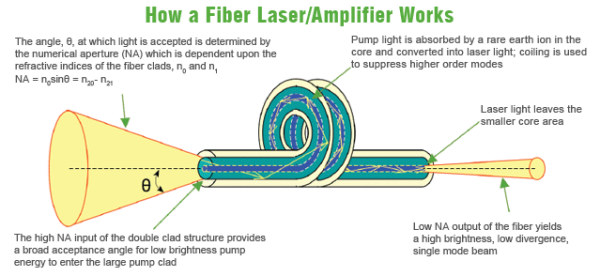
Semiconductor lasers, optical amplifiers and optical fiber lasers from the connector, fusion point, filter the reflection light is very sensitive, and may cause performance deterioration and even damaged, requiring a optical isolator to prevent the reflection of light. The optical isolator is permitted only light along one direction through and in the opposite direction blocks light through the optical passive devices. In the optical fiber communication, optical fiber reflection light through the optical isolator can be a good isolation. In the fiber laser applications, optical isolators are usually used in the optical path to avoid the light path of the light source, the echo on the pumping source and other light emitting device causes interference and damage. Isolators’s isolation represents the optical isolator to echo the isolation (blocking) ability.

2 optical isolator principle

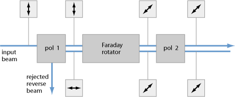
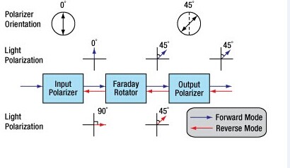
Optical isolator using magnetic optical crystal Faraday effect ( also known as the Faraday effect ). In 1845, Faraday first observed with optical material under the action of magnetic field to make the material in the direction of polarization rotation, therefore often called the Faraday effect. In Faraday effect, the rotation of the polarization direction direction and magnetic field, and the orientation of the light transmitting is independent of the forward and reverse, and we usually in the index of refraction, reflection phenomena seen in the reversibility of optical path difference. Along the magnetic field direction of transmission line polarized, the polarization direction rotating angle θand magnetic field strength of B and L is proportional to the product of the length of the material, the proportion coefficient is what we often say that the Wilde constant. Optical isolator based on polarization characteristics can be divided into polarization-independent and polarization dependent type. These two kinds of isolators are used with the Faraday effect in magneto-optic crystal, Faraday magnetic medium in 1~2μ m wavelength range usually adopts the optical loss low yttrium iron garnet ( YIG ) single crystals. Model of input and output of the fiber optical isolator has fairly good performance, the minimum insertion loss of approximately 0.5 dB, the isolation of up to 35~ 60 dB, a maximum of 70 dB.   The optical isolator using most still is polarization independent type, its principle is shown in Figure 1, using the forward and reverse transmission optical path is inconsistent, it is this time signal transmission is not reversible, thereby forming isolation. The typical structure of only four major components: the magnetic ring, a Faraday rotator, two pieces of LiNbO3 wedge angle piece, with a pair of fiber collimator, can be made into an in-line optical isolators.      

Positive transmission: the parallel light beam from the collimator, into the first wedge angle piece P1, beam is divided into o light and e light, the polarization direction perpendicular to the propagation direction, forming an included angle. When they pass through 45o Faraday rotator, emitted by the o light and e light polarizing surfaces of respective to the same direction of rotation 45o, because the second wedge-shaped plate P2 crystal axis relative to the first wedge angle piece is just in a 45o angle, so o light and e light is refracted into a small space, synthesis. Parallel light, and then by another collimator is coupled to the optical fiber core. In this case, the input optical power only a very small fraction of outage, this loss is called isolator insertion loss.

Reverse transmission: when a beam of parallel light reverse transmission, first with a P2 crystal, divided into the polarization direction and P1 crystal axis respectively in 45o angle o light and E light. Due to the Faraday effect non reciprocity, O Light and e light through the Faraday rotator, the polarization direction to the same direction of rotation 45 °, so the original o light and e light in the second wedge-shaped plate ( P1 ) later became e and O light. Because the refractive index differences, the two light beam in the P1 no longer possible synthesis of a parallel beam of light, but in different directions to the refraction of light, e and o are further separated from a larger perspective, even after a GRIN lens coupling, can not enter the fiber core to, from and achieved reverse isolation purposes. The transmission loss is bigger, this loss is called isolators isolation.

3 main technical parameters of optical isolator

The optical isolator, the main technical indicators have insertion loss, reverse isolation, return loss, polarization dependent loss, polarization mode dispersion.

(1) insertion loss ( Insertion Loss ): isolator core mainly comprises a Faraday rotator and a two piece of LN wedge angle piece, a Faraday rotator extinction ratio higher, lower reflectivity, absorption coefficient is smaller, insertion loss is smaller, general Faraday rotator loss is about 0.02~ 0.06dB. Parallel light pass through the isolator core, will be divided into o, e beams of parallel light. Due to the inherent characteristics of birefringent crystals, O Light and e light can not fully converge, which may cause additional insertion loss.

(2) reverse isolation ( Isolation ): reverse isolation isolator is one of the most important indicators, which characterizes the isolator on the reverse transmission attenuation ability. Effect of isolator isolation of many factors : 1 ) the isolation and polarizer from the Faraday rotator is related to the distance; 2) isolation and optical element surface reflectance relationship. Isolator optical element surface reflectance is bigger, the isolation degree is worse. The practical technology that R must be less than 0.25%, to ensure the isolation degree is greater than 40 dB; 3) isolation of polarimeter and wedge angle, spacing. Double refraction crystal yttrium vanadate ( YVO4 ) of the optical isolator, when the wedge angle of less than 2°, isolation with the perspective of the increase, when the wedge angle is greater than 2°, change is much smaller, approximately stable at about 43.8 dB. Optical isolation with the increase of the distance between the change range is not big, because isolation depends mainly on the reverse output light and the angle between the optical axis; 4) isolation and crystal axis angular relationship relative. The two polarizers and rotator crystal axis relative angle to the isolation effect is maximum, when the angle is greater than the difference between the 0.3o isolation will not be greater than 40 dB; 5) the two polarizer extinction ratio, crystal thickness on isolation effect; 6) the influence of temperature and magnet. In Faraday effect, Verdet constant is a function of temperature, so the Faraday rotation angle will change with the temperature, and the temperature will be on permanent magnet performance impact, so it is one of important factors.

(3) return loss ( Return Loss ): optical return loss refers to the positive incident to the isolator optical power and along the input path to return to the isolator input port of the optical power ratio, this is one of the important indicators, because the echo intensity, isolation would be affected by. Isolator echo loss by each element and the air refractive index mismatch caused by the reflection. The generally planar element caused by echo return loss is controlled in 14 dB, through antireflective film and surface polishing can make the return loss reached more than 60 dB. Optical return loss mainly from the collimated light path (i.e., collimator parts), through the theoretical calculation when the slant angle 8 °, return loss is greater than 65 dB.

(4) the polarization-dependent loss ( Polarization Dependent Loss, PDL ) :PDL and insertion loss is different, it is a when the input light polarization state changes and other parameters unchanged, the insertion loss of maximum variation, is a measure of device insertion loss by effect of polarization degree index. The polarization-independent optical isolator, the device has some may cause polarization components, impossible to achieve PDL is zero, a generally accepted PDL is less than 0.2 dB.

(5) the polarization mode dispersion ( Polarization Mode Dispersion, PMD ) :PMD is defined through the device of the signal light with different polarization states of the phase delay between, in high speed optical communication system is very important in PMD. In optical passive devices, different polarization modes have different propagation paths and different propagation speed, produce corresponding polarization mode dispersion. At the same time, because the light source spectrum lines have a certain bandwidth, can also cause certain dispersion. In a polarization-independent optical isolator, birefringent crystal to produce two beams linearly polarized light in different phase velocity and group velocity of transmission, which is PMD, its main source is used for separation and convergence o light and e light of birefringent crystal. It can be made of two linearly polarized optical path differenceΔ L approximation. PMD is mainly affected by E and O optical refractive index difference, therefore also has great relationship with wavelength.

4 key technologies of high power isolator

Compared with the common optical fiber communication system in the use of low power optical isolator is compared, in the high power laser, optical isolator design and production also exhibit differences, it is also in high power device is designed to solve the main problems in the development of.

(1) the optical element at a high power density laser radiation damage problems. Not only is this problem in a high power optical isolator in existence, is the other high power optical device design process is also to face. In order to solve this problem, first of all need to products in the production and testing process to ensure good environmental cleanliness and selects the damage threshold of high optical device and optical thin films, of course it is cost constraint. Because the air in the tiny particles if adhesion in optical surface will greatly reduce the laser damage threshold of optical surface, these tiny particles on laser absorption is relatively large, easily lead to particle near the energy is concentrated, resulting in optical surface film damage even surface damage, the element surface pitting and even small pit to device failure. Secondly, because in most cases within the optical element damage threshold than the surface laser damage threshold is much higher, so the surface of the laser power density is determined by the whole device resisting laser damage ability, especially in the pulse work situation is even more so. This can be through optical transform method to make optical element surface spot area expansion method to increase the damage threshold, such as expanded core fiber and beam expanding lens optical method is the use of the principle of work, or by changing the laser pulse stretching method to reduce the power density of laser, laser energy in space and by avoiding time of concentration can effectively improve product for resisting laser damage properties.

(2) the high power device for thermal effects and thermal design. Because of the high power device to work in a higher power, and low power devices compared, easy fever, inevitably subjected to temperature rise, so the device performance by the thermal characteristics and thermal design to compare the effects of severe. Usually the optically active crystal optical rotation characteristic of easily affected by temperature, if the device is operating due to the absorption of laser energy accumulation and lead to internal temperature appears bigger rise, will make the optically active crystal on light polarization plane rotation angle deviations from normal values and lead to significant performance loss, serious and even lead to damaged devices; in addition, the permanent magnet at work under high temperature but also more prone to field weakening and demagnetization phenomenon, appear even the magnetic field of the irreversible loss, so the high temperature to the permanent magnet steady work is negative; and, in case of high optical power, optical element temperature will appear bigger rise, due to heat from the inside to the conveying surface, its internal the temperature is above its surface temperature, so that it will in the optical component internal temperature gradient and thermal stress, causing the beam cross-sectional internal center of the refractive index and the edge of the refractive index change in different extent, appear thereby the refractive index difference, also is the emergence of lens effect, it will change the beam propagation characteristics, leading to beam quality drops badly, seriously affect the normal work and even cause damage to device. Therefore, we must take effective measures to reduce the absorption of laser radiation and effective. To reduce the absorption of laser selected absorption coefficient smaller optical materials, Ko Hikaru in the components inside the transmission distance, reasonable structure design, effective heat dissipation requirements may arise in heat accumulation place provides effective heat transfer path and heat dissipation, according to the size of power can adopt a passive or active heat radiation method. The million kilowatts level optical isolation design on the use of the lath shape of the optically active crystal to improve device cooling temperature control ability.

(3) the magnetic field design for high power isolator. High power optical isolator design another key is the magnetic field and magnet design and selection. In general, the optical isolator is the use of magnetic rotation effect work, so must the optically active crystal with proper magnetic field. In order to energy saving and convenient use, generally by the strong permanent magnetic material to produce a desired magnetic field, the magnetic field and magnet selection and design is very important, on device performance and the cost of. Under normal circumstances required in the optically active crystal space to provide a strong homogeneous magnetic field, so it can reduce the optically active crystal size, high ratio of performance to price, so the requirement in without significantly increasing the device volume in the case of the design of suitable magnet to obtain a strong homogeneous magnetic field. In specific design, through the choice of magnetic strong magnets, and adopt suitable shape and volume, to obtain the required magnetic field.

(4) High power optical isolator assembly process. High power optical isolator can work stably for a long time in bad environment, this device structure and assembly process raised very tall requirement. Design of the structure and assembly technology can effectively reduce the optical components of the internal stress, thereby improving the product performance and stability, allows the device to long-term stable and reliable work. Isolator structure design mainly need to solve two problems, first is the optical components of the assembly, stable and reliable heat dissipation requirements, can effectively control; second is firm and reliable assembly of strong permanent magnet, with the magnet design and manufacturing capabilities, devices may use more complex shape of the magnet pieces combined to provide a strong homogeneous magnetic field, between the magnets and strong magnetic requires the design of suitable assembly method and reliable assembly magnet, and required in the assembly process causes no damage or the magnet demagnetization. These need to be accumulated in practice and improve.

Above only briefly in the high power optical isolator design process often encounter some problems, along with applications to expand and deepen, may be needed for isolator corresponding improvement or design to meet the technical and market development, in this process may occur early in the design of possibly unforeseen problems, this requires us to according to the specific circumstances to provide the corresponding solutions, only in this way can we continue to design excellent performance to meet the application needs of the high power optical isolator.
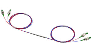
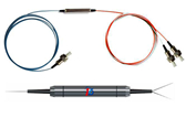
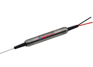
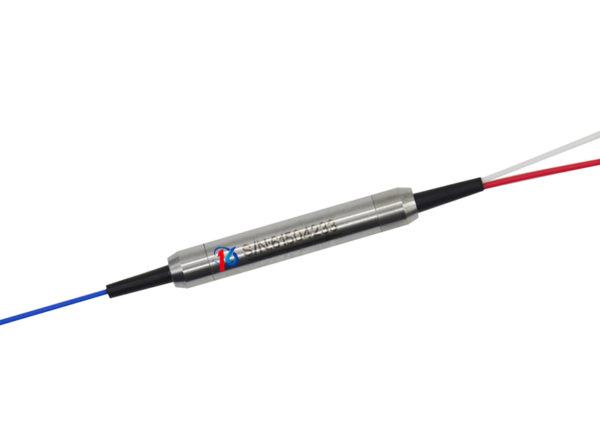
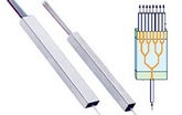
SC fiber optic connector basic structure 

More than a dozen types of fiber optic connectors have been developed by various manufacturers since 1980s. Although the mechanical design varies a lot among different connector types, the most common elements in a fiber connector can be summarized in the following picture. The example shown is a SC connector which was developed by NTT (Nippon Telegraph and Telephone) of Japan.

SC ConnectorA SC Connector Sample


sc connector
SC Connector Structure

Elements in a SC connector

1. The fiber ferrule.

clip_image006_0001SC Connector Fiber Ferrule

SC connector is built around a long cylindrical 2.5mm diameter ferrule, made of ceramic (zirconia) or metal (stainless alloy). A 124~127um diameter high precision hole is drilled in the center of the ferrule, where stripped bare fiber is inserted through and usually bonded by epoxy or adhesive. The end of the fiber is at the end of the ferrule, where it typically is polished smooth.

2. The connector sub-assembly body.

The ferrule is then assembled in the SC sub-assembly body which has mechanisms to hold the cable and fiber in place. The end of the ferrule protrudes out of the sub-assembly body to mate with another SC connector inside a mating sleeve (also called adapter or coupler).

3. The connector housing

Connector sub-assembly body is then assembled together with the connector housing. Connector housing provides the mechanism for snapping into a mating sleeve (adapter) and hold the connector in place.

4. The fiber cable

Fiber cable and strength member (aramid yarn or Kevlar) are crimped onto the connector sub-assembly body with a crimp eyelet. This provides the strength for mechanical handing of the connector without putting stress on the fiber itself.

5. The stress relief boot.

Stress relief boot covers the joint between connector body and fiber cable and protects fiber cable from mechanical damage. Stress relief boot designs are different for 900um tight buffered fiber and 1.6mm~3mm fiber cable.

Several common Kinds Of CWDM Moudules

Coarse Wavelength Divison Multiplexer/Demultiplexer Module (CWDM Mux/Demux) is really a flexible, low-cost solution that effective at combining nine optical signals in to a fiber pair. The CWDM Mux/Demux is designed to interoperate with the WaveReady distinct transponder and optical regenerator solutions as well as CWDM transponders and small form-factor pluggables (SFPs) utilized in acquireable transmission equipment.


Common utilizations of CWDM technology include the multiplexers and de-multiplexers or optical amplifiers to improve the ability in the fiber optic cable. The CWDM Mux/Demux modules including CWDM MUX and CWDM Demux, are designed to multiplex multiple CWDM channels into 1 or 2 fibers. As well as highly reliable passive optics certified for environmentally hardened applications, the CWDM Mux/Demux lets operators use available fiber bandwidth in local loop and enterprise architectures.


In accordance with the wavelength or running channels in the each signal, CWDM MUX/DEMUX includes 4CH, 5CH, 8CH, 9CH, 16CH, 18CH CWDM Mux/Demux. These CWDM MUX/DEMUX can be found in 19 Rack Mount or LGX module package.


CWDM MUX/DEMUX Module general features:

w   Low Insertion Loss;

w   Low PDL;

w   Compact Design;

w   Good channel-to-channel uniformity;

w   Wide Operating Wavelength;

w   Wide Operating Temperature;

w   From -40??C to 85??C;

w   High Reliability and Stability.


CWDM MUX/DeMUX Module Applications:

w   CWDM System;

w   PON Networks;

w   CATV Links.


CWDM supplies the most economic and efficient wavelength division multiplexing solutions for metro edge and access networks.DK Photonics CWDM products cover 2 channel, 4 channel, 5 channel, 8 channel, 9 channel, 16 channel and 18 channel CWDM Mux/Demux.DK Photonics Technology offers CWDM OADMs (Optical Add/Drop Module) from 1 to 16 channels for CWDM networks, including 1 channel, 2 channel, 4 channel, 8 channel and 16 channel CWDM OADM.


The CWDM OADMs are passive devices that can multiplex/demultiplex or add/drop wavelengths from multiple fibers onto one optical fiber. Through the use of CWDM technology, individual channels might be optically added or dropped from a fiber pair while allowing pass-through visitors to continue unobstructed through the bus or ring. It offers low insertion loss, high channel isolation, wide pass band, low temperature sensitivity and epoxy free optical path.


CWDM OADM Key Features:

w   Add/drop ITU-T G.695- and G.694.2-compatible CWDM channels onto a fiber pair;

w   Designed for use in outside-plant fiber splice enclosures;

w   Upgradeable to 8 channels per fiber;

w   Provides low-loss pass-through for CWDM channels;

w   Thermally stable passive optics require no electrical energy.


CWDM OADM Applications:

w   Provides fiber conservation or reclamation for CWDM wireless backhaul, broadband, and other services;

w   Supports linear (bus) and ring add/drop architectures 

 How are Optic Fiber Made?

Many People ask how fiber optics are made. You can’t just use “regular” glass. If you were to make optical fiber from ordinary window glass, the light that you shine through it would have a difficult time traveling more than a few kilometers, let alone the distances necessary for long distance transmission. That’s because ordinary glass contains distortions, discolorations and other impurities that would quickly absorb, reflect, or otherwise disperse light long before it could travel any great distance.

In contrast, because optical fiber is actually made from very pure glass, the light traverses great distances largely unimpeded by impurities and distortions.

Fiber Optic Cable – Light How it Works

To transmit light effectively, fiber optic cable must contain glass of the highest purity. The process of making glass with this level of purity is very demanding, requiring careful control over the materials and processes involved. Yet, the fundamental concept is simple. Essentially, optical fiber is made from drawing molten fiber from a heated glass blank or “preform.” The following provides a more detailed explanation of the three basic steps involved in making optical fiber.

Step #1

Create the Fiber Optic Preform

A preform is a cylindrical glass blank that prides the source material rom optic fiberwhich the glass fiber will be drawn in a single, continuous strand.

Making a preform involves a chemical process known as Modified Chemical Vapor Deposition (MCVD). This process involves bubbling oxygen through various chemical solutions including germanium chloride (GeC14) and silicon chloride (SiC14).

The bubbling chemicals produce gas that is directed into a hollow, rotating tube made of synthetic silica or quartz. A torch is moved up and down the rotating tube, resulting in very high temperatures that cause the gas to react with oxygen to form silicon dioxide (Si02) and germanium dioxide (Ge02). These two chemicals adhere to the inside of the rotating tube where they fuse together to form extremely pure glass.

Creating the preform takes several hours, after which additional time is required for the glass blank to cool. Once cooled, the glass is tested to ensure that it meets quality standards, especially in terms of index of refraction.

Step #2

Draw Optical Fiber from the Preform

In this step, the finished glass preform is installed at the top of a tower which supports various devices used in the fiber drawing process.

The process begins by lowering one end of the preform into an in-line furnace that produces heat in a range of 3,400 to 4,000 degrees Fahrenheit. As the lower end of the preform begins to melt, it forms a molten glob that is pulled downward by gravity. Trailing behind the glob is a thin strand of glass that cools and solidifies quickly.

The equipment operator threads this glass strand through the remainder of the devices on the tower, which include a number of buffer coating applicators and ultraviolet curing ovens. Finally, the operator connects the fiber to a tractor mechanism.

The tractor device pulls the glass strand from the preform at a rate of 33 to 66 feet per second. The actual speed at which the tractor pulls the strand is dependent upon the feedback information the device receives from a laser micrometer that continually measures the fiber’s diameter.

At the end of the run, the completed fiber is wound onto a spool.

Step # 3

Test the Fiber Optics

The completed optical fiber must undergo a number of tests to determine the quality of the finished product. The following are a few of the assessments involved:

• Refractive index profile

• Fiber geometry inspection, including core, cladding and coating

• Tensile strength • Bandwidth capacity

• Attenuation at different wavelengths

• Chromatic dispersion

• Operating temperature and humidity range


Quality Control in Optical Fiber Production

Various factors influence the quality and purity of the optical fiber produced. These include: Chemical Composition – Achieving optimal ratios of the various chemicals used to create the preform is important for achieving glass purity. This mixture of chemicals also determines the optical properties of the fiber that will be produced from the preform, including coefficient of expansion, index of refraction, and so forth. Gas Monitoring – It is crucial that the gas composition and rate of flow be monitored throughout the process of creating the preform. It is also important that any valves, tubes and pipes that come into contact with the gas be made of corrosion-resistant materials.

Heat and Rotation – The hollow cylinder that is used to create the preform must be heated at the proper temperature and continually rotated to enable the chemicals to be deposited evenly.

Relationship Between The Optical Coupler And PLC Splitter

In fact, splitter is named for the function of the device, coulper named for its working principle, splitter may be based coupler, and may be based on the waveguide or the separating element, coupler can be done either the splitter, but also can be done WDM, attenuator.

Optical coupler either split optical signals into multiple paths or combines multiple signals on one path. Optical signals are more complex than electrical signals, making optical couplers trickier to design than their electrical counterparts. Like electrical currents, a flow of signal carriers, in this case photons, comprise the optical signal. However, an optical signal does not flow through the receiver to the ground. Rather, at the receiver, a detector absorbs the signal flow. Multiple receivers, connected in a series, would receive no signal past the first receiver which would absorb the entire signal. Thus, multiple parallel optical output ports must divide the signal between the ports, reducing its magnitude. The number of input and output ports, expressed as an N x M configuration, characterizes a coupler. The letter N represents the number of input fibers, and M represents the number of output fibers. Fused couplers can be made in any configuration, but they commonly use multiples of two (2 x 2, 4 x 4, 8 x 8, etc.).

PLC Splitter is a device that split the fiber optic light into several parts by a certain ratio. The simplest couplers are PLC Splitters. These devices possess at least three ports but may have more than 32 for more complex devices.PLC Splitters are important passive components used in FTTX networks. But two kinds of fiber splitters are popular used, one is the traditional fused type PLC Splitter (FBT splitter), which features competitive prices; the other is PLC PLC Splitter, which is compact size and suit for density applications. Both of them have its advantages to suit for different requirement.

PLC Splitter typical parameter include input and output part cable length, splitting ratio, working wavelength and with what kind of fiber optic connectors. Just like fiber patch cable, fiber splitters are usually with 0.9mm, 2mm or 3mm cables. 0.9mm outer diameter cable is mostly used in stainless steel tube package PLC Splitters, while 2mm and 3mm cables are mostly used in box type package fiber splitters. Based on working wavelength difference there are single window and dual window PLC Splitters. And there are single mode fiber splitter and multimode fiber splitter. Typical connectors installed on the PLC Splitters are FC or SC type.

Optical coupler or PLC splitters are available in a selection of styles and sizes to separate or combine light with minimal loss. All couplers are produced employing a proprietary procedure that produces reliable, low-cost devices. They’re rugged and impervious to common high operating temperatures. Couplers can be fabricated with custom fiber lengths or with terminations of any type.

Application of optical communication is still broad prospects


Once the Nortel global leader in fiber optic communications during the Internet bubble in 2000, the money in the acquisition of a large number of optical communications research and the production of small and medium enterprises, the industry has been criticized in the subsequent bankruptcy of Nortel. In fact, Nortel grasp of technology trends, the direction is right, unfortunately, Nortel too hasty, global demand for optical communication was not to such an extent

But now the situation is very different compared with around 2000. The rapid development of mobile Internet and the widespread popularity of smart mobile terminal equipment, being a huge challenge to the global telecommunications network capacity, transmission speed. The era of “data flood peak to optical communication technology has always been known by the transmission bit of new development opportunities and a huge space. Optical communication technology not only did not fall behind, the contrary, the optical communication industry chain, from fiber optic cable system equipment, terminal equipment to optical devices, a critical period in the comprehensive technology upgrade

The field of optical communication is a noteworthy event, the National Development and Reform Commission recently organizing the preparation of strategic emerging industries key products and services Guidance Catalogue, which in conjunction with the relevant departments, the optical communication technology and product responsibility and selected emerging industries of strategic focus products.

In fiber optics, including FTTx G.657 optical fiber, broadband long-distance high speed large capacity optical fiber transmission with G.656 optical fiber, photonic crystal fiber, rare earth doped fiber (including ytterbium doped fiber, erbium doped fiber and thulium doped fiber, etc.) the laser energy transmission fiber, and has some special properties of new optical fiber, plastic optical fiber, polymer optical fiber is fully finalists. The upgrade of the fiber optic technology, will bring the data transmission capacity, distance, quality leap

In the field of fiber access equipment, passive optical network (PON), wavelength division multiplexer (WDM),OLT and ONU on the list. Optical transmission equipment, especially the line rate of 40 Gbit/s, 100Gbit/s large capacity (1.6Tb/s and abobe) DWDM equipment, reconfigurable optical bifurcation Multiplexer (ROADM) wavelength division multiplexing system ran cross-connect (OXC) equipment, large-capacity high-speed OTN optical transport network equipment as well as packetized enhanced OTN equipment, PTN packet transport network equipment also impressively. These products are “broadband China” works to promote a powerful weapon; both long-distance backbone network, metropolitan area network or access network even close to the user’s “last mile” of these products will come in handy.

The major products are classified as strategic emerging industries in the field of optical devices, high-speed optical components (active and passive). This is the core and foundation of the field of optical communication technology, device development, the improvement of integration, function enhancement can bring significantly reduce the cost of system equipment and provide a performance boost.

At the same time, the annual OFC / NFOEC (fiber-optic communications exhibition) will be held in late March in California. This event will showcase the latest technology and research progress of the global optical component modules, systems, networks and fiber optic products, represents a new trend of development of optical communication technology

100G for ultra-high-speed network technology is the current OFC hot one. 2012 100G technology on a global scale backbone network level scale application of 100G optical network applications will rapidly expand with the 100G device further mature. In the same time, the industry has also increased efforts to develop the 100G optical modules, silicon photonics technology pluggable multi-source agreement 100G CFP MSA CPAK optical module has been available. Outside the backbone network, 100G MAN application is the current one of OFC discussion topic.

The rise of cloud computing brings data center construction boom, 100G technology in the data center is a popular data center for high-speed pluggable optical devices is also a hot topic. Experts believe that photonic technology has a key role to play in the large enterprise data centers, but this is only a start, the size of the new cloud computing data center such as a warehouse, with more than 100,000 servers carrying the computing and storage resources, the required network bandwidth than PB level. These data centers only optical communications technology in order to achieve VCSEL (vertical cavity surface emitting lasers) and multi-mode fiber has played an important role, and will continue to introduce new fiber optic communication technology.


 What is WDM? What Is the Difference Between DWDM and CWDM Optical Technologies?

What is WDM?

In the same optical fiber at the same time can let two or more than two wavelength signal transmit and receive information through different optical channel, called wavelength division multiplex, referred to as WDM. Wavelength division multiplexing includes frequency division multiplexing and wavelength division multiplexing. Optical frequency division multiplexing (FDM) technology and optical wavelength division multiplexing (WDM) technology has no obvious difference, because the light is part of the electromagnetic wave, frequency and wavelength of light have a single correspondence. Usually also can understand so, optical frequency division multiplexing mean subdivision of optical frequency, very dense optical channel. Wavelength division multiplexing means divided frequency of light, light channel far apart, even in the optical fiber with different window.

The general application of division multiplexing wavelength is respectively using a wavelength division multiplexer and demultiplexer arranged at both ends of the optical fiber, coupling and separation of different wavelength. The main four types of WDM are fused biconical taper type, dielectric film type, FBG type and planar waveguide grating type .The main characteristic is the insertion loss and isolation. Usually, the optical link using wavelength division multiplexing equipment, increase the amount of optical link loss is called WDM insertion loss. When the wavelength transmission through the same optical fiber, the D-value between the splitter input mixed power and the output end of the fiber power is called isolation.. The following are characteristics and advantages of optical wavelength division multiplexing technical:

(1) Make full use of low loss band fiber, increase the transmission capacity of optical fiber, the physical limit of an optical fiber for transmitting information doubled to several times. At present, we only use the low loss optical fiber spectrum (1310nm-1550nm) a few, WDM can fully utilize the huge bandwidth of single-mode fiber is about 25THz, the transmission bandwidth is sufficient.

(2) There are ability to transmit  two or more than two asynchronous signal in the same optical fiber ,there are compatible for digital and analog signals, has nothing to do with the data rate and modulation mode, the middle line can be removed or added channel.

(3) About the optical fiber system that has built, especially early laying optical cable that core number not much, as long as the original system power is margin, we can increase the capacity; realize the transmission of multiple one-way or two-way signals without making big changes to the original system, so it has strong flexibility.

(4) Due to the large number of reducing use amount of the fiber, it can greatly reduce the construction cost, because the fiber quantity is less, when a fault occurs, the recovery is also fast and convenient.

(5) Sharing of active optical devices, the cost of transmission of multiple signals or increase new business will reduce.(6)The active devices in the system have been substantially reduced, which improves the reliability of the system. At present, because of the light multi carrier division multiplexing of optical transmitter, optical receiver equipment's requirements higher, technology implementation has certain difficulty, also multiple core cable used in traditional broadcast television transmission business does not appear especially shortage, so the practical application of WDM is still not much. However, with the development of CATV integrated service development, the growing demand for network bandwidth, all kinds of selective service upgrade and network implementation economic cost considerations and so on, the characteristics and advantages of WDM in the CATV transmission system gradually emerged, showing broad application prospects, even influence the development pattern of CATV network.


What Is the Difference Between DWDM and CWDM Optical Technologies?

DWDM (dense wavelength division multiplexing) is undoubtedly the first choice technology in the field of fiber optic applications today, But the cause of high cost make many do not bounteous operators hesitating. Is there a lower cost for using the wavelength division multiplexing technology? In the face of this demand, CWDM (coarse wavelength division multiplexing) emerges as the times require.

CWDM, just as its name implies, is a dense wavelength division multiplexing next of kin, the difference between CWDM and DWDM mainly has two points: first, the CWDM carrier channel spacing is wider, therefore, light in a single fiber can reuse about 5 to 6 wavelengths, that is where the "dense" and "coarse" appellation come from; Two, CWDM modulation laser using uncooled laser, but DWDM is used in cooling laser. Cooling laser using temperature tuning, uncooled laser adopts electronic tuning. Because the range of temperature distribution is nonuniform in a very wide wavelength, so the temperature tuning is very difficult to realize, the cost is very high. CWDM avoids this problem, so it greatly reduces the cost; the whole CWDM system cost only 30% of DWDM.

CWDM provides a very high access bandwidth with a low cost, suitable for point to point, Ethernet, SONET rings and all kinds of popular network structure, especially suitable for short distance, high bandwidth, access point intensive, communication applications, such as network communication between the building or building. It is particularly worth mentioning is that CWDM with the use of PON (passive optical network).PON is a cheap, one-point to multi-point optical fiber communication mode, in combination with the CWDM, each individual wavelength channel can be used as virtual optical link of PON, Implementation of broadband data transmission between center node and multiple distributed nodes.

There are several companies are offering CWDM related products at present. However, CWDM is a product of cost and performance tradeoffs; inevitably there are some performance limitations. Industry experts point out, at present the CWDM have four following disadvantages: first, CWDM in a single fiber support multiplexing wavelength number is minor, leading to future expansion cost is high; second, multiplexing, multiplexing equipment cost should also be reduced, the device cannot be simply modified of DWDM corresponding equipment; third, CWDM does not apply to metropolitan area network, the distance between metropolitan area network nodes is short , the money that operators use in CWDM equipment expansion can be used to laying more fiber, and get better effect; fourth, CWDM has not yet formed standards.

What’s more, something about the WDM products.

(1)CWDM Mux/Demux module

CWDM Mux and CWDM Demux are designed to multiplex multiple CWDM channels into one or two fibers. The core of CWDM Module application is the passive MUX DEMUX unit. The common configuration is 1×4, 1×8, 1×16 channels. Available in 19″ Rack Mount or LGX module package. Optional wide band port is available to multiplex with CWDM Channels wavelength.

(2)DWDM Mux/Demux Modules

DWDM Mux and DWDM DeMux are designed to multiplex multiple DWDM channels into one or two fibers. The common configuration is 4, 8, 16 and 40 channels. These modules passively multiplex the optical signal outputs from 4 or more electronic devices, send them over a single optical fiber and then de-multiplex the signals into separate, distinct signals for input into electronic devices at the other end of the fiber optic link

(3)Optical Splitter-- a important component in EPON network

Optical splitter in optical communication era is a component of EPON network construction, is a connection of OLT and ONU passive device.

Its function is to distribute the downlink data, and focus on the uplink data. Optical splitter has an upstream optical interface, a plurality of downlink optical interface. Optical signals from the upstream optical interface over was assigned to the downstream optical interface out all transmissions, optical signals from the downlink optical interface over being allocated to uplink optical interface out transmission only. The light intensity signal downlink optical interface of each can be same, can also be different.


  • DK Photonics' Blog is to introduce fiber optical passive components.we provide many features, application and description of them in detail for all of you. 
 

Make a free website with Yola